Using Offset Assemblies in Civil 3D: A Complete Guide for Smarter Corridor Design
Designing complex corridors in Autodesk Civil 3D can be challenging, especially when you encounter varying widths, curving alignments, or independent paths such as bike lanes or sidewalks. One of the most powerful techniques for handling these challenges is Offset Assemblies. By leveraging offset assemblies, engineers can create more flexible, efficient, and accurate corridor designs without overcomplicating their main assembly.
In this comprehensive guide, Civil Designs explain what offset assemblies are, how they differ from traditional assemblies, the benefits they offer, and practical tips for using them effectively in real-world projects.
What is an Offset Assembly in Civil 3D?
An offset assembly is a secondary assembly that runs parallel to your main corridor baseline but is placed at a specified horizontal offset. Unlike traditional assemblies, which are tied directly to a single baseline, offset assemblies allow you to model additional corridor features that require independent control over alignment and profile.
Think of it as adding a separate lane of logic to your corridor. This method is particularly useful for features like:
- Bike paths
- Sidewalks
- Service roads
- Shoulders and medians
Offset assemblies enable you to model these features without affecting your primary corridor design, keeping your project organized and error-free.
Why Use Offset Assemblies?
Civil engineering projects rarely follow perfectly straight paths. Roads widen, bike paths curve independently, and intersections introduce complex geometry. Using offset assemblies allows you to handle these situations with precision and flexibility.
Key Benefits of Offset Assemblies:
- Improved Design Flexibility – Handle varying widths, lane additions, or independent paths without cluttering your main assembly.
- Cleaner Corridor Models – Keep your primary corridor simple while modeling complex features separately.
- Accurate Volume Calculations – Maintain precise cross-section and material calculations for each offset feature.
- Independent Profile Control – Elevation and grading logic can be unique for each offset assembly.
also check This Civil 3D Mistake Happens to Everyone
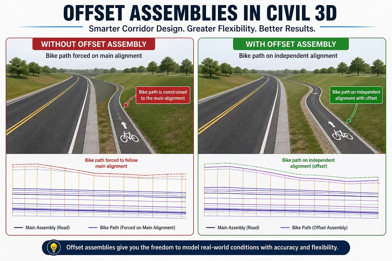
Real-World Example: Modeling a Bike Path
Imagine you are designing a road with an adjacent bike path that doesn’t maintain a constant offset. Terrain constraints, property boundaries, and design regulations may cause the bike path to shift along its length.
If you attempt to model this using a single baseline:
- You may face calculation errors.
- Volume computations become unreliable.
- The design becomes harder to manage and modify.
The Solution:
Use an offset assembly for the bike path.
Advantages:
- The bike path can have its own alignment independent of the road.
- Vertical profiles are controlled separately for precise grading.
- Cross-sections and material volumes are accurate and reliable.
- Design modifications to the bike path do not affect the main road corridor.
How Offset Assemblies Work in Civil 3D
Offset assemblies consist of two key components:
1. Alignment
The alignment defines the horizontal path of the offset feature. It can follow the main corridor closely or diverge entirely to fit independent design requirements.
2. Profile
The profile controls the vertical design (elevation) of the offset assembly. Each offset profile can have unique slope, grading, or elevation logic, separate from the main corridor.
Types of Offset Assemblies
Single Offset Assembly
Used for features like:
- Bike paths
- Sidewalks
- Service roads
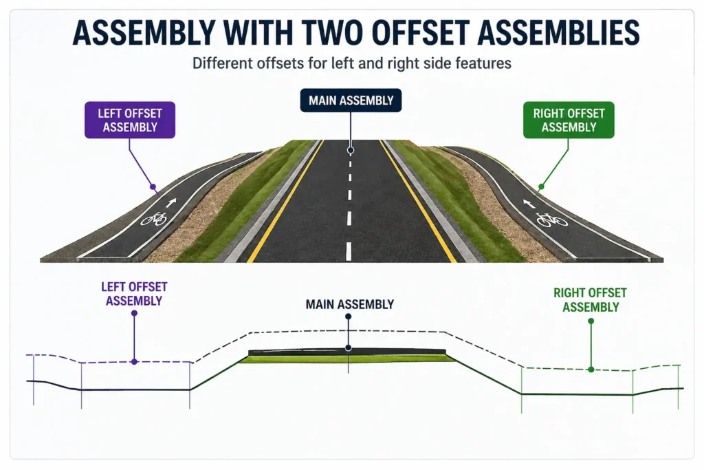
Multiple Offset Assemblies
Complex corridors often require multiple offsets in one model. Examples include:
- Left widening lanes
- Right shoulder extensions
- Central median variations
Each offset assembly can have:
- Its own alignment
- Its own profile
- Independent design logic, materials, and grading
Offset Assembly vs Traditional Assembly
| Feature | Traditional Assembly | Offset Assembly |
|---|---|---|
| Baseline | Single | Multiple |
| Flexibility | Limited | High |
| Complex designs | Difficult | Easy |
| Independent profiles | No | Yes |
Key Takeaway: Offset assemblies provide greater flexibility, particularly for projects with variable geometries or multi-feature corridors.
Important Limitations
- Offset assemblies cannot directly use the same alignment and profile as the main assembly.
- If you need to replicate profiles from your main corridor, you can use the Superimposed Profile tool to copy elevations effectively.
Best Practices for Using Offset Assemblies
To maximize the benefits of offset assemblies:
- Keep the main assembly simple – Avoid adding complex features that can be modeled as offsets.
- Use offsets for variable elements – Such as widening, lanes, sidewalks, and medians.
- Maintain clear naming conventions – Distinguish each offset for easy management.
- Align profiles carefully – Ensure vertical continuity and accurate grading.
- Check sections frequently – Validate cross-sections and volume calculations for each offset.
- Document your design logic – Helps when sharing models or collaborating with other engineers.
When Should You Use Offset Assemblies?
Use offset assemblies for projects that involve:
- Road widening or lane additions
- Independent bike or pedestrian paths
- Complex intersections or ramps
- Multi-corridor designs
- Features that do not follow a constant offset
Advanced Tips for Smart Corridor Modeling
- Combine multiple offset assemblies for large projects with several independent elements.
- Use dynamic constraints to automatically adjust offsets based on alignment changes.
- Integrate offset assemblies with data shortcuts to maintain collaboration across multiple engineers and offices.
- Regularly audit corridor models to ensure that offset assemblies remain consistent with design standards.
Final Thoughts
Offset assemblies are not just a convenience—they are a fundamental technique for professional Civil 3D users. They allow you to model corridors in a smarter, cleaner, and more realistic way. By mastering offset assemblies, you can:
- Reduce errors
- Improve design efficiency
- Maintain independent control of complex features
- Deliver professional, construction-ready models
For engineers serious about improving their Civil 3D workflow, mastering offset assemblies is essential.
Want More Civil 3D Tips?
Stay connected with Civil3DPro for expert guides, tutorials, and practical workflows designed specifically for real engineers. From corridor modeling to grading, surface creation, and visualization, we provide actionable tips to help you design smarter and faster.


One Comment