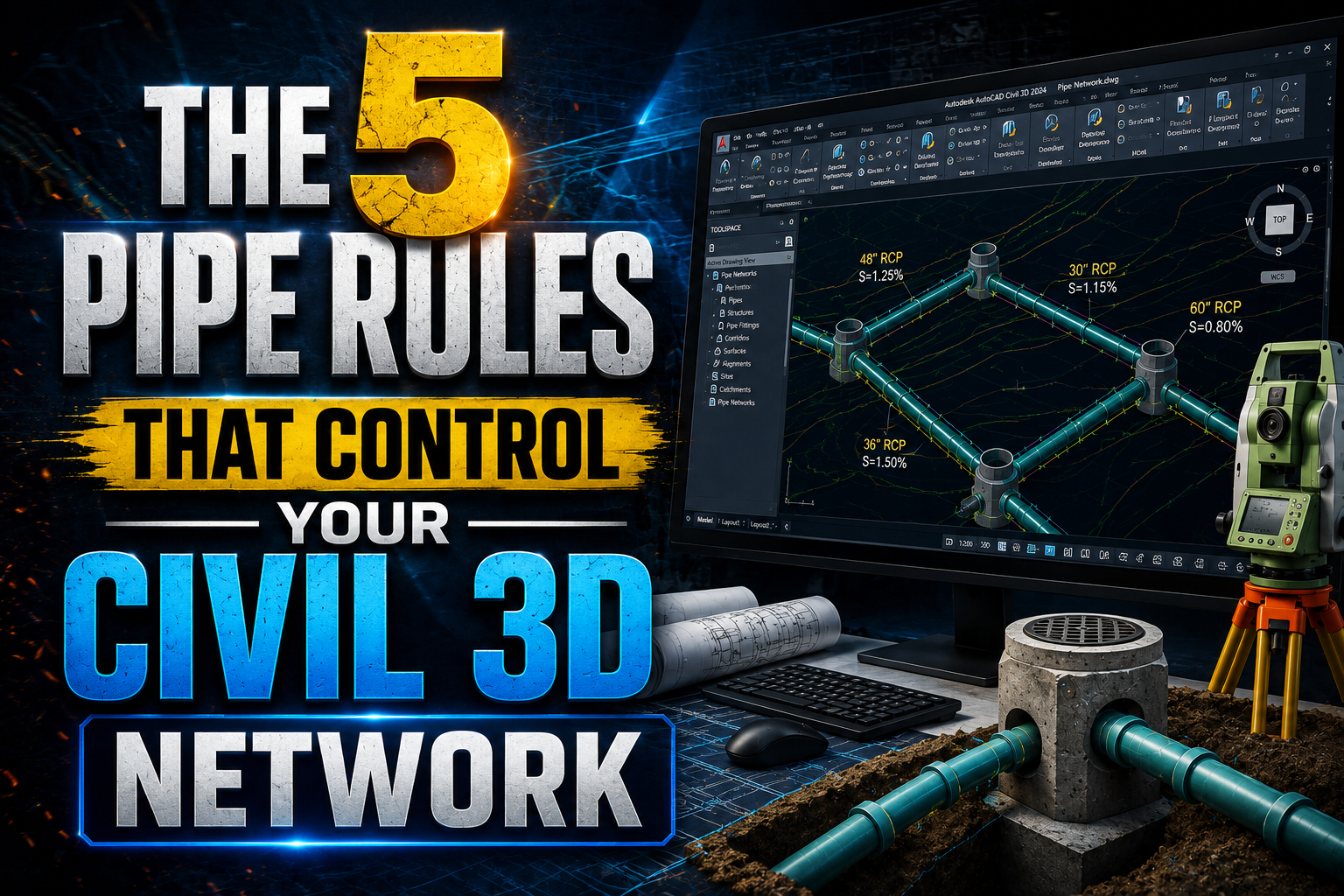
The 5 Pipe Rules That Control Your Civil 3D Network
When designing a drainage system in AutoCAD Civil 3D, Pipe Networks provide the tools needed to create pipes, structures, and connected drainage systems. But simply creating the network is not enough. Engineers also need to understand how Civil 3D evaluates pipe geometry and identifies conditions that may not meet the design requirements.
This is where Pipe Network Rules become important.
Pipe Network Rules allow Civil 3D to evaluate different aspects of a pipe network, including pipe cover, slope, length, pipe-to-pipe connections, and pipe end locations.
Understanding these rules can make it much easier to review a drainage network and understand why Civil 3D may report a rule violation.
What Are Pipe Network Rules?
A Pipe Network Rule is a set of parameters that tells Civil 3D what conditions should be checked or maintained for a pipe.
Different rules are designed for different purposes.
For example, you may want to make sure that:
- A pipe has enough cover
- The pipe slope stays within an acceptable range
- Pipe lengths are not excessive
- Directly connected pipes have the correct invert relationship
- Pipe ends are positioned correctly relative to structures
Instead of treating all of these conditions as one rule, Civil 3D provides separate rules for different design requirements.
1. Cover and Slope Rule
The Cover and Slope Rule is one of the most important Pipe Network Rules for drainage design.
It combines two major pipe design requirements:
Cover — the amount of material above the pipe.
Slope — the vertical change along the pipe relative to its horizontal length.
The rule allows you to specify four values:
- Maximum Cover
- Minimum Cover
- Maximum Slope
- Minimum Slope
For example, the figure shows:
Maximum Cover: 10.00 ft
Minimum Cover: 3.00 ft
Maximum Slope: 8.00%
Minimum Slope: 1.00%
What Does This Mean?
The pipe is expected to remain within the specified cover and slope ranges.
For example, if the minimum cover is 3 ft, a pipe with only 2 ft of cover would fall below the specified requirement.
Similarly, if the minimum slope is 1%, a pipe designed at 0.5% would fall outside the specified slope range.
The same concept applies to the maximum values.
If the pipe becomes excessively deep or its slope becomes too steep, Civil 3D can identify the condition as a rule violation.
Why Is This Rule Useful?
Cover and slope are critical in drainage design.
Adequate cover may be required to protect pipes from surface loads and construction conditions, while the appropriate slope is important for achieving the intended hydraulic performance.
The actual values should always be selected according to the project requirements and applicable engineering standards.
2. Cover Only Rule
The Cover Only Rule is similar to the cover portion of the Cover and Slope Rule, but it focuses specifically on pipe cover.
This rule allows you to specify:
- Maximum Cover
- Minimum Cover
The example shown in the figure uses:
Maximum Cover: 30.00 ft
Minimum Cover: 3.00 ft
How Does Cover Only Work?
Imagine a pipe has a minimum cover requirement of 3 ft.
If the pipe has:
3.5 ft cover → within the specified range.
2.5 ft cover → below the minimum.
35 ft cover → above the maximum.
Civil 3D can identify conditions outside the specified range.
When Is Cover Only Useful?
There are situations where pipe slope may vary based on the design, but the engineer still wants to maintain a specific range of pipe depths.
In that situation, a Cover Only Rule can be useful because it focuses on the cover requirement rather than establishing a slope range.
3. Length Check Rule
The Length Check Rule is used to check the length of a pipe.
The figure shows:
Maximum Length: 200.00 ft
Minimum Length: 1.00 ft
The purpose of this rule is to identify pipe lengths that fall outside the specified range.
Example
Suppose the maximum pipe length is set to 200 ft.
If your pipe is:
150 ft → within the range.
200 ft → at the maximum limit.
250 ft → exceeds the maximum and can be identified as a violation.
The same concept applies to the minimum length.
Important Difference
The Length Check Rule is a checking rule.
It does not automatically resize your pipe simply because the pipe violates the length requirement.
Instead, it helps you identify the condition so you can review the design and make an engineering decision.
This can be especially useful when reviewing large Pipe Networks where manually checking every pipe length would take significant time.
4. Pipe to Pipe Match Rule
The Pipe to Pipe Match Rule is designed for situations where one pipe connects directly to another pipe without a structure between them.
When two pipes meet directly, Civil 3D needs to determine how their pipe inverts should relate to each other.
The example shows:
Match Location: Invert
Drop Value: 0.00 ft
What Is the Invert?
The invert is the elevation at the inside bottom of the pipe.
For drainage systems, invert elevations are extremely important because they determine how water flows through the network.
Match Location: Invert
When the match location is set to Invert, Civil 3D uses the pipe invert when determining the relationship between the two connected pipes.
Drop Value
The Drop Value specifies the vertical difference that should be applied between the connected pipe inverts.
With a value of:
0.00 ft
there is no additional drop specified.
If a project requires a particular vertical difference between directly connected pipes, the drop value can be configured accordingly.
When Is This Rule Useful?
This rule is particularly useful for Pipe Networks where pipes connect directly to other pipes without an intermediate structure.
It helps maintain a predictable relationship between their invert elevations.
5. Set Pipe End Location Rule
The Set Pipe End Location Rule controls where the end of a pipe is positioned relative to a structure.
This becomes important because a pipe connecting to a structure can be referenced using different locations.
For example, the pipe can be associated with the:
- Structure Center
- Structure Inner Wall
- Structure Outer Wall
The rule also provides options such as:
Start Offset
and
End Offset
Why Does Pipe End Location Matter?
Consider a pipe entering a manhole.
If the pipe is measured from the center of the manhole to the center of another structure, the reported pipe length may not represent the physical distance between the actual pipe openings.
In some projects, you may instead want the pipe end to be located at the inside wall of the structure.
The Set Pipe End Location Rule provides greater control over this relationship.
Understanding the Difference Between These Rules
One of the easiest ways to understand Pipe Network Rules is to look at what each rule is actually responsible for.
Cover and Slope
Checks both pipe cover and pipe slope.
Cover Only
Checks pipe cover without defining a slope range.
Length Check
Checks whether the pipe length falls within the specified limits.
Pipe to Pipe Match
Controls the relationship between directly connected pipe inverts.
Set Pipe End Location
Controls where the pipe ends relative to a structure.
Each rule has a different purpose, so understanding the difference is important when reviewing Pipe Network behavior.
A Practical Storm Sewer Example
Imagine you’re designing a storm sewer network for a residential development.
You may have the following design criteria:
Minimum Cover: 3 ft
Maximum Cover: 10 ft
Minimum Slope: 1%
Maximum Slope: 8%
Maximum Pipe Length: 200 ft
These criteria can be reflected through appropriate Pipe Network Rules.
During the design process, suppose one pipe is created with:
Cover = 2.5 ft
Civil 3D can identify that the pipe is below the specified minimum cover.
Now imagine another pipe has:
Slope = 0.5%
If the minimum slope is 1%, the pipe can also be identified as being outside the rule range.
If another pipe is:
250 ft long
while the maximum length is 200 ft, the Length Check Rule can identify the problem.
This makes Rule Sets particularly useful during design review and quality control.
Why Pipe Network Rules Are Important
Large drainage networks can contain dozens or even hundreds of pipes and structures.
Manually checking every pipe for cover, slope, length, and connection conditions can take a considerable amount of time.
Pipe Network Rules provide a systematic way to check these conditions.
They can help engineers:
- Identify potential design violations
- Maintain consistent design criteria
- Review large networks more efficiently
- Reduce repetitive manual checking
- Improve pipe network quality
- Understand problematic pipe conditions
- Speed up the design review process
However, rules should support engineering judgment rather than replace it.
A rule violation does not automatically mean that the design is technically wrong. There may be project-specific reasons why a pipe does not meet a particular rule.
Rule Violations in Civil 3D
When a pipe does not satisfy a rule, Civil 3D can report the condition as a rule violation.
For example:
A pipe may have insufficient cover.
A pipe may have a slope outside the specified range.
A pipe may exceed the maximum length.
Two directly connected pipes may not match according to the selected Pipe to Pipe Match settings.
A pipe end may not be positioned according to the required structure location.
These violations give the designer an opportunity to review the network and determine whether a correction is necessary.
Don’t Treat Every Violation the Same
This is an important point when working with Pipe Network Rules.
A violation should be reviewed in the context of the project.
For example, a pipe with less than the specified minimum cover may need to be lowered.
But there may be a situation where lowering the pipe would create another problem, such as a conflict with an existing utility.
Similarly, a pipe may exceed the recommended length because of site constraints.
Therefore, Pipe Network Rules should be used as a design and quality-control tool, not as a substitute for engineering judgment.
Best Way to Understand Pipe Rules
When reviewing a Pipe Network Rule, ask three simple questions:
What does this rule check?
Determine whether it applies to cover, slope, length, connection, or pipe location.
What happens if the rule is violated?
Some rules primarily identify violations, while other rules can influence pipe geometry or positioning.
Does the rule match my project requirements?
Always compare the rule values with the actual project specifications and applicable standards.
This approach makes it much easier to understand why Civil 3D is reporting a particular condition.
Final Thoughts
Pipe Network Rules are an essential part of understanding how Civil 3D evaluates drainage pipe designs.
The Cover and Slope Rule deals with pipe cover and slope, while the Cover Only Rule focuses specifically on cover. The Length Check Rule evaluates pipe length, the Pipe to Pipe Match Rule controls the relationship between directly connected pipe inverts, and the Set Pipe End Location Rule controls how pipe ends relate to structures.
Understanding these rules allows Civil 3D users to interpret Pipe Network violations, review drainage designs more efficiently, and make better engineering decisions.
The most important thing is to understand what each rule is actually checking rather than simply applying rules without knowing their purpose.
When used correctly, Pipe Network Rules can become a valuable part of your Civil 3D drainage design and quality-control workflow.