Planning a Wastewater Pipe Network in Civil 3D: A Complete Guide
Designing a wastewater pipe network in Autodesk Civil 3D is not simply a matter of drawing pipes and connecting manholes. A successful design starts with proper planning—understanding the local jurisdiction’s requirements, defining pipe and structure behavior, establishing minimum slopes and cover requirements, and deciding how the network will be represented in plan and profile views.
Before creating a Civil 3D Pipe Network, it is important to organize all of these design requirements in advance. This makes the modeling process faster, more accurate, and much easier to maintain throughout the project.
In this Guice, we will look at how to plan a typical wastewater network before building it in Civil 3D.
Why Wastewater Pipe Network Planning Is Important
A wastewater system normally consists of:
- Wastewater pipes
- Manholes
- Cleanouts
- Pipe connections
- Inverts and rims
- Required slopes
- Minimum cover
- Plan and profile representations
If these requirements are not established before starting the Civil 3D model, you may have to repeatedly modify pipe sizes, slopes, structures, styles, and network rules later.
A better approach is to first create a wastewater design checklist based on the requirements of the applicable city, county, or utility authority.
Once the requirements are defined, they can be incorporated into your Civil 3D template and Pipe Network Parts List.
- Start With the Local Wastewater Design Requirements
The first step is to determine the wastewater standards for the jurisdiction where the project is located.
Different municipalities and utility providers can have different requirements for:
- Minimum pipe diameter
- Minimum pipe slope
- Minimum cover
- Manhole dimensions
- Manhole structure types
- Cleanout requirements
- Invert drops
- Pipe materials
- Pipe connection details
- Plan/profile drafting standards
For example, a typical wastewater specification may recommend 8-inch (200 mm), 10-inch (250 mm), and 12-inch (300 mm) PVC pipes, subject to the manufacturer’s specifications and local standards.
The important point is that these values should not simply be copied from another project. They should always be checked against the current requirements of the project jurisdiction.
- Establish Minimum Wastewater Pipe Slopes
Pipe slope is one of the most important parameters when planning a wastewater network.
Gravity wastewater systems depend on sufficient slope to maintain flow through the pipe. Therefore, the minimum allowable slope should be established before creating the Pipe Network in Civil 3D.
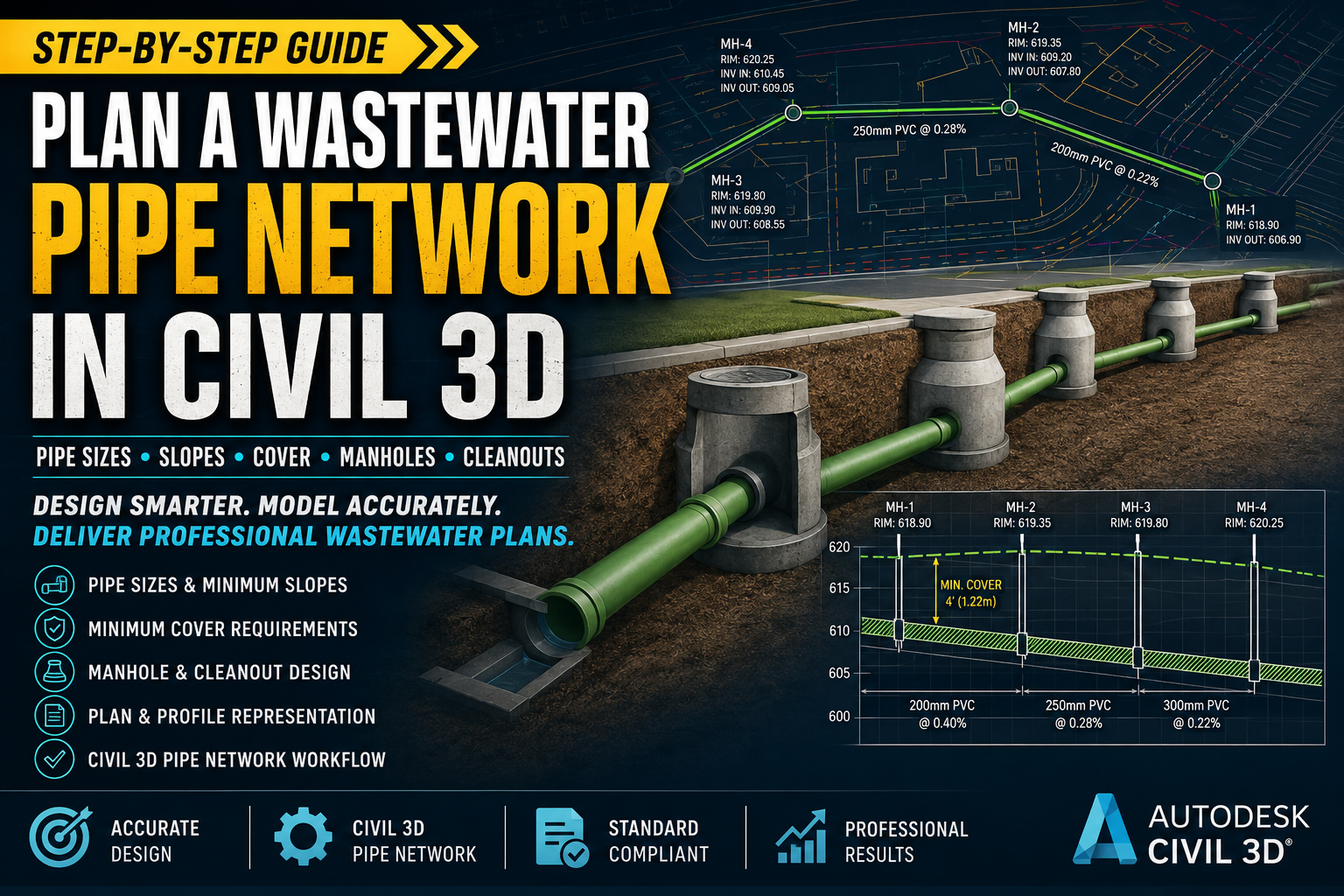
For example, the referenced Sample County requirements show the following minimum slopes:
| Pipe Size | Minimum Slope |
|---|---|
| 8 in. (200 mm) | 0.40% |
| 10 in. (250 mm) | 0.28% |
| 12 in. (300 mm) | 0.22% |
These values mean that an 8-inch pipe, for example, should generally not be designed below a 0.40% slope unless the governing authority allows otherwise.
Why minimum slope matters
If the slope is too flat, the wastewater system may not achieve the desired hydraulic performance or self-cleansing velocity.
During Civil 3D design, these minimum slopes can be used as design checks when establishing pipe inverts between structures.
- Consider Maximum Pipe Slope
Minimum slope is not the only consideration.
The referenced requirements indicate that the maximum slope for pipes is 10 percent, although minimum slopes may be adjusted to optimize velocity where permitted.
A very steep wastewater pipe can create excessive flow velocities and may introduce other design or maintenance concerns.
Therefore, while modeling the network in Civil 3D, both minimum and maximum slope requirements should be considered.
A good workflow is:
Pipe Size → Minimum Slope → Maximum Slope → Required Cover → Structure Elevations
This helps you establish realistic pipe elevations before beginning detailed profile design.
- Maintain the Required Pipe Cover
Another important requirement is the minimum cover over the wastewater pipe.
In the referenced example, wastewater pipes must have a minimum cover of 4 feet (1.22 m) to the top of the pipe.
This means the vertical distance between the finished grade and the top of the pipe should generally not be less than the required cover.
In Civil 3D
This requirement becomes particularly important when designing the network profile.
You need to check:
- Existing ground profile
- Proposed finished grade profile
- Pipe crown elevation
- Pipe invert elevation
- Pipe diameter
- Minimum required cover
For example:
Finished Grade Elevation − Pipe Crown Elevation ≥ Required Cover
Maintaining adequate cover helps protect the pipe from surface loads and provides sufficient depth for the utility system.
- Plan the Wastewater Structures
A wastewater network is not made up of pipes alone. Structures such as manholes and cleanouts must also be planned before creating the Civil 3D Pipe Network.
In the referenced example, the recommended structures include:
- Standard concentric manholes
- Small-diameter cleanouts
The structure requirements also specify that wastewater structures have:
- A 1.5 ft (0.50 m) sump
- A 0.10 ft (0.03 m) invert drop across all structures
- Rim elevations based on the finished road grade
These parameters are extremely useful when configuring Civil 3D structure rules and parts.
- Understand Manhole and Cleanout Behavior
Before modeling, you should understand how each structure behaves in the network.
Manholes
Manholes provide access to the wastewater system and are typically placed at locations such as:
- Changes in pipe direction
- Changes in pipe slope
- Changes in pipe diameter
- Pipe intersections
- Required maintenance/access locations
In the example shown in the reference material, manholes have a standard sump and invert-drop requirement.
Cleanouts
Cleanouts are smaller access structures and may be used where permitted by the governing wastewater standard.
The Civil 3D model should represent these structures differently from standard manholes so that the plan and profile drawings clearly communicate their purpose.
- Plan How the Network Will Be Represented in Civil 3D
Civil 3D does more than calculate pipe elevations. It also controls how the wastewater system appears in construction documents.
Therefore, Pipe Network Styles and Structure Styles should be planned before production.
For example, in plan view:
- Wastewater pipes can be represented using a CENTER2-type linetype
- Manholes can be represented as circles with an identifying symbol
- Cleanouts can be represented using a different symbol or hatch pattern
In profile view, pipes can be displayed using both their inner and outer walls, with hatching between the walls to represent pipe thickness.
This makes the final plans much easier to read.
- Configure the Civil 3D Pipe Network Parts List
Once the design requirements are known, the next step is to translate those requirements into the Civil 3D Parts List.
A typical wastewater Parts List may include:
Pipes
- 8-inch PVC
- 10-inch PVC
- 12-inch PVC
Structures
- Standard wastewater manhole
- Cleanout
- Other jurisdiction-specific structures
The exact parts should depend on the project’s governing standards.
This is where a properly configured Civil 3D template can save significant time. Instead of configuring the same pipe sizes, structures, layers, styles, and labels for every project, you can build them into your template.
- Create a Wastewater Network Design Checklist
Before starting the actual Pipe Network, I recommend creating a checklist similar to the following:
Wastewater Pipe Requirements
- Pipe material
- Available pipe diameters
- Minimum slope
- Maximum slope
- Minimum cover
- Pipe wall thickness
- Manufacturer requirements
Structure Requirements
- Manhole type
- Cleanout type
- Manhole sump depth
- Invert drop
- Rim elevation requirements
- Structure dimensions
Civil 3D Requirements
- Pipe Parts List
- Structure Parts List
- Pipe Network Styles
- Structure Styles
- Label Styles
- Plan/Profile display settings
- Layer standards
This checklist can then be used as the foundation for the Civil 3D model.
- Build the Wastewater Network in Civil 3D
After planning and configuring the requirements, you can begin creating the actual Pipe Network.
A typical workflow is:
Survey / Existing Surface
↓
Proposed Finished Grade
↓
Determine Wastewater Alignment
↓
Place Manholes & Cleanouts
↓
Select Pipe Sizes
↓
Set Pipe Slopes
↓
Check Minimum Cover
↓
Create Profiles
↓
Check Inverts & Connections
↓
Apply Styles & Labels
↓
Prepare Plan & Profile Sheets
This approach helps prevent major revisions later in the design process.
- Check the Wastewater Network in Profile View
The profile view is one of the most important parts of wastewater design.
After creating the network, review:
- Existing ground
- Proposed finished grade
- Pipe invert elevations
- Pipe crown elevations
- Pipe slopes
- Structure rims
- Structure inverts
- Minimum cover
- Pipe crossings
- Connections between structures
Civil 3D makes it much easier to identify problems visually in profile view.
For example, if a pipe is too shallow, you can immediately see the relationship between the finished grade and the pipe crown.
- Final Quality Control Before Plan Production
Before issuing the wastewater plans, perform a final QA/QC review.
Check that:
Pipe Design
- Correct pipe sizes are used
- Minimum slopes are satisfied
- Maximum slopes are not exceeded
- Required cover is maintained
- Pipe materials comply with project standards
Structures
- Correct manhole types are used
- Cleanouts are correctly represented
- Rim elevations match the design requirements
- Invert drops are correct
- Pipe connections are properly modeled
Drawings
- Pipe labels are correct
- Structure labels are correct
- Plan view symbols are clear
- Profile view is readable
- Pipe styles are correct
- Structure styles are correct
- Notes and details match the applicable standards
Conclusion
Planning is the most important step before creating a wastewater Pipe Network in Civil 3D.
Instead of immediately drawing pipes and structures, first identify the jurisdiction’s requirements for pipe sizes, minimum and maximum slopes, cover, manholes, cleanouts, invert elevations, and drafting standards.
Once these requirements are organized, they can be incorporated into your Civil 3D Parts List, Pipe Network Styles, Structure Styles, and template.
This approach creates a more consistent workflow and reduces the amount of editing required during the design process.
A well-planned Civil 3D wastewater network should ultimately connect three things:
Design Standards + Civil 3D Configuration + Engineering Judgment
When these three are properly coordinated, the Pipe Network becomes much easier to model, review, and convert into professional wastewater plan and profile drawings.