Civil 3D Pipe Network Vista: The Faster Way to Edit Large Drainage Networks
When a Civil 3D pipe network contains only a few pipes and structures, editing individual objects is relatively easy. But what happens when your storm drainage network contains 50, 100, or even several hundred pipes and structures?
Opening the properties of every pipe one by one is slow, repetitive, and highly prone to mistakes.
This is where the Civil 3D Pipe Network Vista becomes extremely useful.
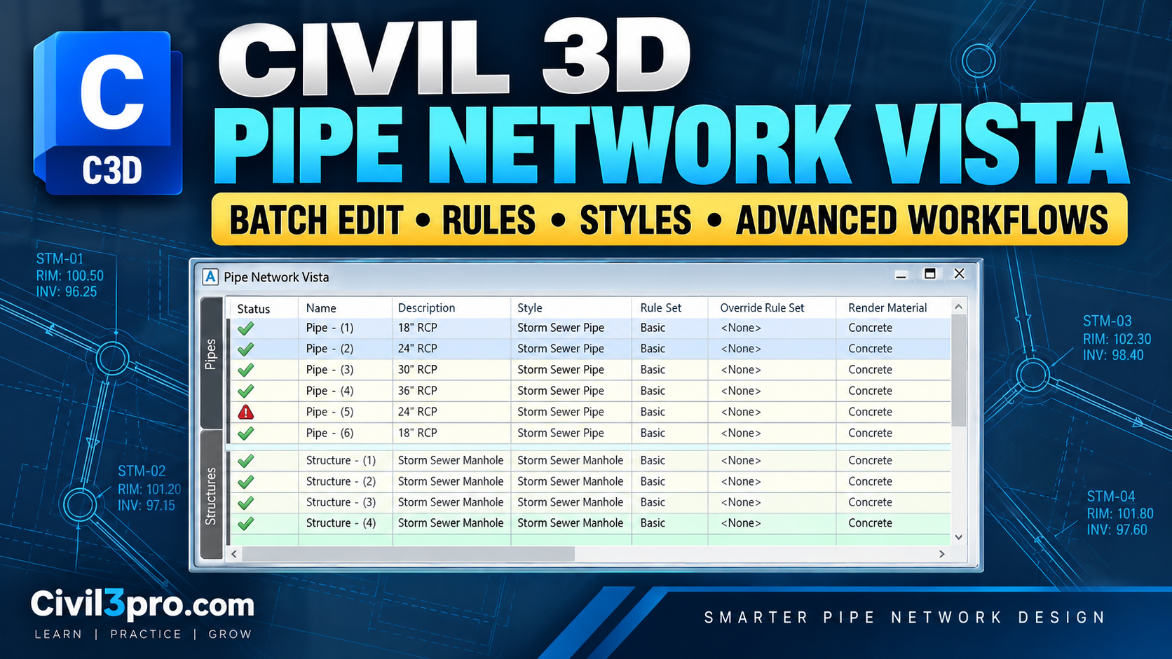
The Pipe Network Vista provides a spreadsheet-style interface where pipes and structures can be reviewed and edited in rows and columns. Instead of navigating through the drawing and opening dozens of individual property dialogs, you can make many changes directly from one centralized interface. Autodesk describes the Vista as a way to view and edit pipe network components through the Panorama window.
The real power, however, is not simply viewing the network.
The real advantage is batch editing.
What Is the Civil 3D Pipe Network Vista?
The Pipe Network Vista is essentially a table-based management interface for your pipe network.
When you open a network in the Vista, Civil 3D separates the components into:
- Pipes
- Structures
Each object appears as a row, while properties such as name, description, style, rule set and other parameters appear as columns.
This makes the Vista particularly valuable for projects where consistency matters.
For example, imagine a storm sewer network containing:
- 75 pipes
- 32 manholes
- Multiple pipe sizes
- Different structure styles
- Several descriptions
- Multiple rule sets
Instead of editing these objects individually, you can select multiple rows and apply certain changes simultaneously.
Autodesk’s documentation confirms that the Vista works similarly to a spreadsheet and allows users to customize columns, select objects and edit available properties.
How to Open the Pipe Network Vista
A typical workflow is:
Toolspace → Prospector → Pipe Networks → Select Network → Edit Network
Alternatively, select a pipe or structure in the drawing, right-click and choose Edit Network. From the Network Layout Tools, you can access the Pipe Network Vista.
Once opened, you’ll see the network components organized in a tabular interface.
The important thing is to understand that not every cell is editable.
Some properties are controlled by Civil 3D, while others can be modified directly. Disabled or shaded cells indicate values that cannot be edited from that particular Vista.
- Batch Edit Pipe and Structure Styles
One of the most useful applications of the Pipe Network Vista is bulk style management.
Suppose your drainage design contains 80 pipes and you realize that they were assigned the wrong pipe style.
Editing them individually would be unnecessary.
Instead:
- Select the required rows.
- Right-click the appropriate column.
- Choose Edit.
- Select the desired value/style.
- Apply the change.
This approach is especially useful when preparing drawings for different deliverables.
For example, you might maintain:
Design Style → Plan Production Style → Profile Style → Construction Documentation Style
Rather than modifying every object separately, batch editing lets you standardize the network much faster.
Autodesk also documents batch property changes through the Prospector item view, where multiple pipes or structures can be selected and their styles, rules or render materials changed together.
- Batch Change Pipe Descriptions
Descriptions are often underestimated in Civil 3D projects.
But when you are working with large networks, consistent descriptions become extremely useful for:
- Quantity takeoffs
- Construction documentation
- QA/QC
- Filtering
- Data extraction
- Project coordination
Imagine that 40 pipes need the description:
STORM SEWER – 18″ RCP
Instead of opening 40 property dialogs, select the required rows and edit the Description column.
This is one of those small Civil 3D techniques that can save a surprising amount of time on production projects.
- Use the Status Column as a QA/QC Tool
This is where Pipe Network Vista becomes more than just an editing interface.
The Status column can indicate whether a pipe or structure has a rule violation.
A warning symbol means that Civil 3D has identified a condition that violates one or more assigned rules. Autodesk notes that rule violations can appear in the Pipe Network Vista and in the Rules tab of the relevant properties dialog.
For example, a pipe may violate:
- Minimum cover
- Maximum length
- Minimum slope
- Maximum slope
- Pipe diameter requirements
- Structure connection requirements
Instead of checking every pipe manually, the Vista gives you a quick way to identify objects requiring attention.
Advanced QA/QC Workflow
A good workflow is:
Design → Open Pipe Network Vista → Check Status → Investigate Warnings → Review Rules → Correct Geometry → Recheck Network
This turns the Vista into a simple but powerful network QA/QC dashboard.
- Understand the Difference Between Rules and Manual Edits
This is one of the most important concepts when working with Civil 3D pipe networks.
Civil 3D rules primarily control how pipe and structure elevations and other properties are established during creation or modification. A rule violation can generate a warning without necessarily preventing you from completing the edit.
For example, imagine your pipe has a required minimum cover of 3.0 ft.
You manually raise the pipe.
The pipe may still exist in the drawing, but Civil 3D can flag the object because the minimum cover rule has been violated.
Important: A warning does not automatically mean that the geometry is impossible. It means the object should be reviewed against the rules you’ve assigned.
This distinction is critical for professional drainage design.
- Don’t Blindly “Fix” Every Rule Warning
This is an advanced Civil 3D concept that many beginners overlook.
A rule warning is an indicator, not necessarily an instruction to blindly change the geometry.
Consider a pipe crossing another utility.
You may intentionally have a condition where the standard minimum cover or elevation relationship is not satisfied because of an existing constraint.
In such cases:
Review the engineering condition first, then decide whether the rule violation should actually be corrected.
This is why experienced Civil 3D users don’t simply eliminate every warning symbol without understanding its cause.
- Pipe Network Rules Are Part of Your Design System
Rules should not be treated as an annoying Civil 3D feature.
They can be used as a design-control framework.
Pipe rules can help establish criteria such as:
- Minimum cover
- Maximum length
- Minimum slope
- Maximum slope
- Minimum depth
- Other project-specific design checks
Structure rules can also control conditions such as:
- Pipe drop across structures
- Maximum pipe size
- Sump depth
- Connection-related requirements
Autodesk documents separate rule behavior for pipes and structures, including structure rules that can influence connected pipe elevations.
Professional Approach
Instead of waiting until the end of the project to discover design problems, configure your rule sets early.
Then use the Pipe Network Vista to monitor violations throughout the design process.
That creates a much stronger workflow:
Design → Automatic Rule Check → Review → Correction → Final QA
- Batch Change Rule Sets
Another advanced use is changing rule sets across selected network components.
Suppose your initial network was created using a generic rule set.
Later, the project requires a more specific drainage standard.
Instead of opening each pipe individually, you can use the network item view/Vista approach to manage properties across multiple selected objects.
This is particularly useful when a project moves from:
Concept Design → Preliminary Design → Detailed Design → Construction Documents
Different project stages may require different display standards and design criteria.
- Manage Render Materials Efficiently
Pipe networks aren’t only about 2D plans.
Civil 3D can display and render pipe network components in 3D, and render materials can be assigned to network parts. Autodesk specifically identifies render material as one of the properties that can be batch changed.
This becomes useful when creating:
- 3D utility coordination models
- Client presentations
- Visualization
- Clash review
- Construction coordination
For example, you could assign consistent materials to different pipe families rather than manually editing each object.
- Use Parts Lists Strategically
Here’s another technique that can dramatically improve pipe network productivity.
Don’t treat the Civil 3D Part Catalog and Parts List as the same thing.
The catalog contains available pipe and structure definitions, while a parts list is a project-specific subset of the available parts. Autodesk recommends using parts lists to restrict the components available for a particular network.
For example, a storm drainage project might use only:
Pipes
- 12″ RCP
- 15″ RCP
- 18″ RCP
- 24″ RCP
- 30″ RCP
Structures
- Standard Catch Basin
- Junction Manhole
- Headwall
Instead of exposing hundreds of irrelevant catalog parts, create a focused parts list.
Why this matters
A controlled parts list:
- Reduces design errors
- Speeds up network creation
- Makes part selection easier
- Standardizes projects
- Improves drawing consistency
- Use One Network for Components That May Need to Connect
A common Civil 3D mistake is creating too many separate pipe networks.
Autodesk recommends considering one network per network type, such as a storm drainage network or sanitary network, particularly when components may eventually need to connect. Components belonging to different networks cannot simply be connected together.
For example:
STORM NETWORK
may contain:
- Inlets
- Manholes
- Storm pipes
- Outfalls
- Headwalls
while:
SANITARY NETWORK
contains:
- Sanitary manholes
- Sanitary sewer pipes
- Cleanouts
This organization makes future editing and rerouting much easier.
- Don’t Forget Surface and Alignment References
A pipe network doesn’t exist in isolation.
Civil 3D pipe networks can reference surfaces and alignments. Surface information can be used to determine elevations and depths when network components are created, while alignments can provide station/offset relationships.
This becomes particularly important when designing:
- Road drainage
- Storm sewer systems
- Subdivision utilities
- Highway drainage
- Urban infrastructure
Advanced Workflow
A strong setup is:
Existing Ground Surface
↓
Proposed Profile / Alignment
↓
Pipe Network
↓
Rules
↓
Plan + Profile + Section Views
↓
QA/QC
This keeps the drainage network connected to the actual design environment instead of treating pipes as isolated CAD geometry.
- Pipe Network Vista + Profile View = Powerful Combination
One of the biggest mistakes beginners make is checking the pipe network only in plan view.
A pipe may look perfectly positioned in plan while being completely wrong vertically.
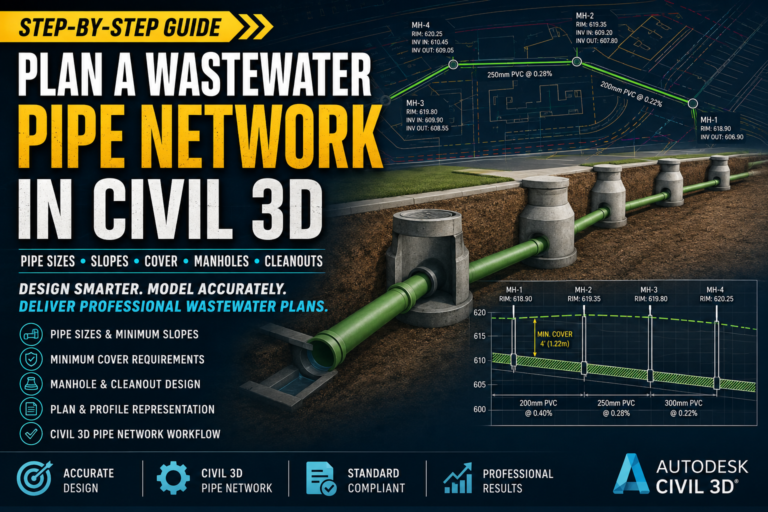
Always review your network in:
Plan View
Check:
- Alignment
- Connectivity
- Horizontal routing
- Structure locations
Profile View
Check:
- Inverts
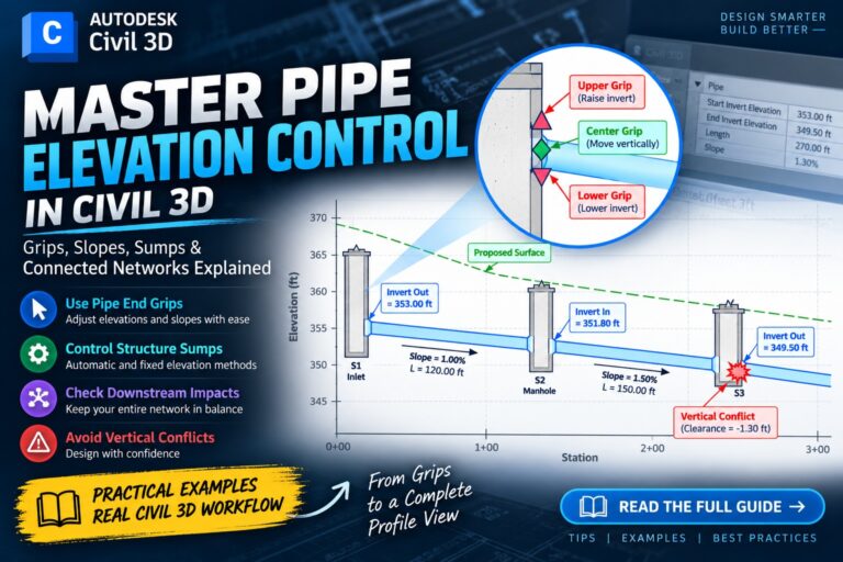
- Slopes
- Cover
- Vertical conflicts
- Pipe crossings
- Structure depths
Section View
Check:
- Utility conflicts
- Road crossings
- Vertical clearances
- Relative pipe positions
Civil 3D supports pipe network visualization in plan, profile and section views, allowing the same network to be evaluated from multiple perspectives.
- Use Interference Checking Before Finalizing the Network
For larger utility projects, don’t stop at rule checking.
Use Interference Checking to identify potential conflicts between pipe network components.
This is especially important where storm, sanitary, water, electrical or other utility systems interact.
A professional workflow should therefore include:
Rule Check + Profile Review + Section Review + Interference Check
rather than relying on a single method.
Autodesk includes interference checking as part of its pipe network analysis workflow.
- The Most Efficient Pipe Network Editing Workflow
If you’re working on a large Civil 3D drainage project, this is the workflow I’d recommend:
Step 1 — Build a Controlled Parts List
Only include the pipe and structure families required for the project.
Step 2 — Set Surface and Alignment References
Make sure the network is connected to the correct design references.
Step 3 — Configure Rule Sets
Establish the project criteria before creating large amounts of network geometry.
Step 4 — Create the Network
Lay out pipes and structures using consistent naming and styles.
Step 5 — Open Pipe Network Vista
Use the tabular interface to inspect the network.
Step 6 — Batch Edit
Standardize:
- Names
- Descriptions
- Styles
- Rule sets
- Render materials
- Other available properties
Step 7 — Review Status
Investigate warning symbols and rule violations.
Step 8 — Review Profile
Verify slopes, inverts and cover.
Step 9 — Check Interferences
Look for conflicts with other network components.
Step 10 — Final Documentation
Generate labels, tables, plan/profile sheets and quantity information.
This workflow can eliminate a huge amount of repetitive clicking on large projects.
A Powerful Civil 3D Tip: Treat the Vista Like a Database
Here’s the mindset shift that separates basic Civil 3D users from advanced users:
Don’t think of Pipe Network Vista as just a table.
Think of it as a database-style management interface for your network objects.
The drawing shows you where the objects are.
The profile shows you how they behave vertically.
The Vista shows you what they are and how their properties are organized.
Together, these three views create a much stronger editing and QA/QC system.
Common Mistakes to Avoid
❌ Editing every pipe individually
Use batch editing whenever the same property needs to be changed across multiple objects.
❌ Ignoring warning symbols
A warning may indicate a genuine design problem.
❌ Automatically fixing every warning
First understand why the rule was violated.
❌ Using an uncontrolled parts list
A huge catalog makes network creation slower and less consistent.
❌ Creating unnecessary separate networks
Keep components that may need to connect within the appropriate network.
❌ Checking only plan view
Always review important drainage networks in profile and, where necessary, section view.
❌ Treating styles as an afterthought
Styles are part of efficient plan production and network management.