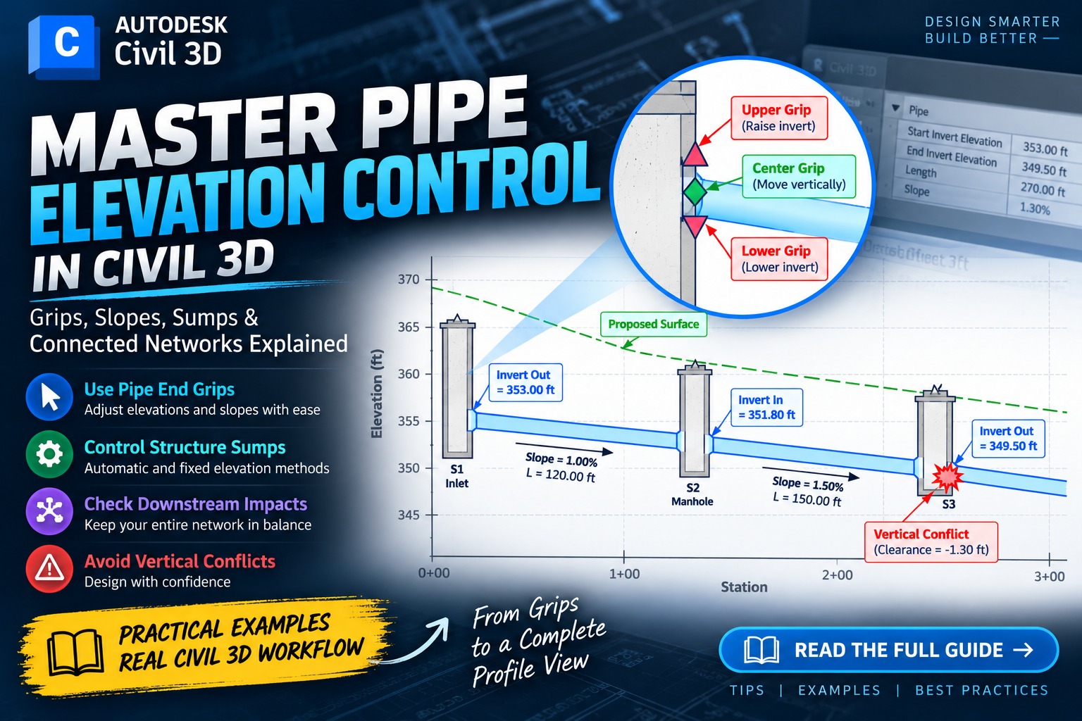
Editing Pipe Networks in Profile View Using Grips in Civil 3D
Editing Pipe Networks in Profile View Using Grips in Civil 3D
Editing a pipe network in Civil 3D becomes much faster when you work directly in Profile View.
Instead of opening the properties of every pipe and structure, Civil 3D provides dedicated grips that let you make vertical adjustments visually. However, these grips do more than simply move objects up and down. Their behavior depends on the properties of the pipe or structure being edited.
For structures, the two most important grips are the Rim Insertion Point grip and the Sump grip. Pipes have grips at their endpoints that can be used to modify their vertical geometry and slope.
Understanding what each grip controls is the key to editing pipe networks without creating unexpected elevations or slopes.
Structure Grips in Profile View
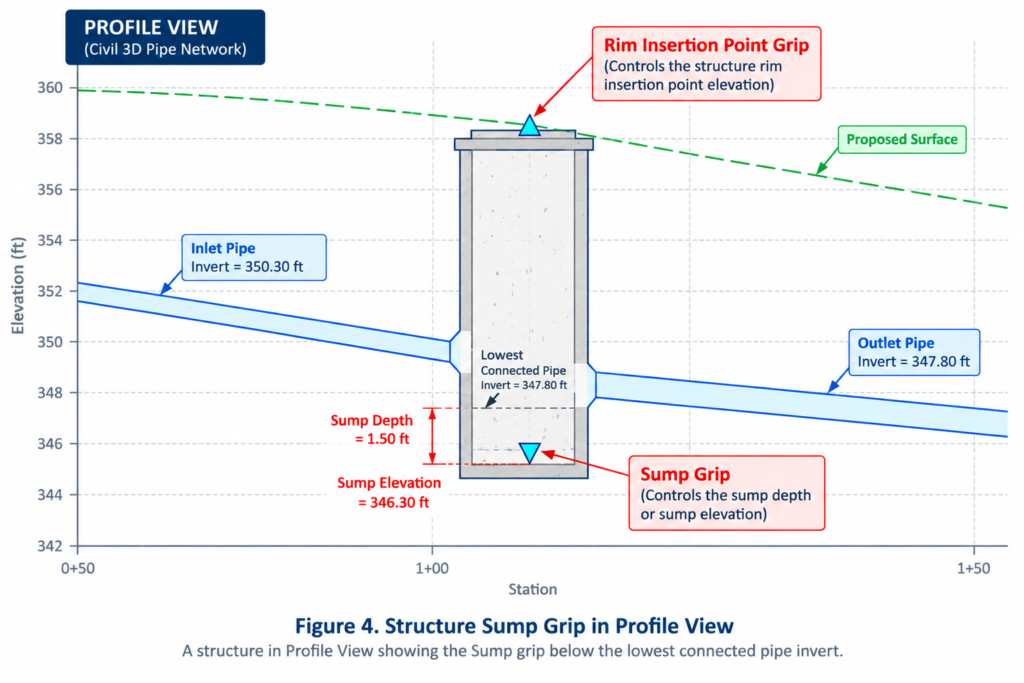
When you select a structure in Profile View, Civil 3D displays two primary grips.
Rim Insertion Point grip
Sump grip
The upper grip controls the vertical position of the structure insertion point, while the lower grip controls the sump.
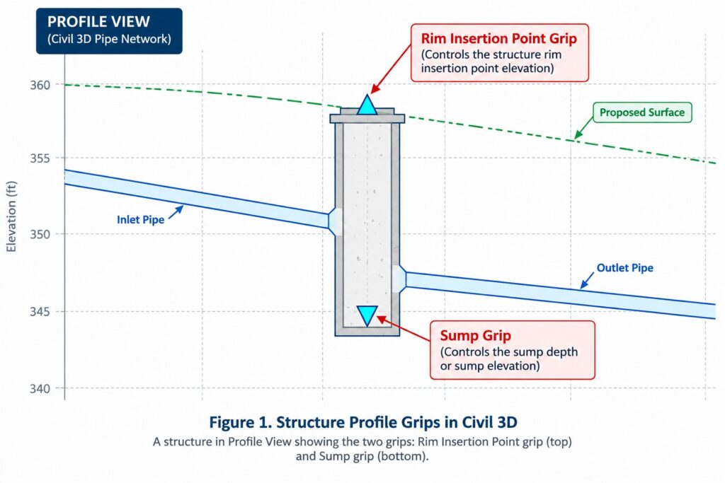
These grips should not be treated as simple “move up/move down” controls. What happens when you move them depends on the structure properties.
- Editing the Structure Rim with the Rim Insertion Point Grip
The Rim Insertion Point grip is the upper grip displayed on the structure.
Dragging this grip vertically changes the structure’s insertion point elevation.
The important question is:
What happens to the rim when you move this grip?
The answer depends largely on the Automatic Surface Adjustment setting.
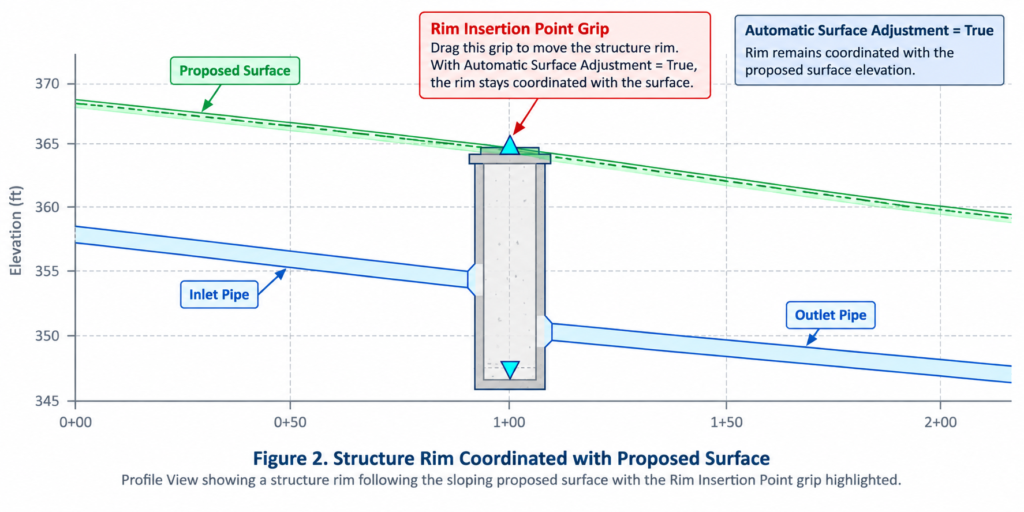
Automatic Surface Adjustment = True
When Automatic Surface Adjustment is set to True, the structure maintains its relationship with the selected reference surface.
This is particularly useful when structure rims need to follow a proposed finished surface.
For example, imagine a storm sewer manhole located beneath a roadway. If the roadway profile changes, you may want the manhole rim to remain coordinated with the finished grade rather than becoming disconnected from the surface.
With Automatic Surface Adjustment enabled, changing the Rim Insertion Point can also change the surface adjustment associated with the structure.
When should you use this?
Automatic Surface Adjustment can be useful when:
Structure rims should follow finished grade.
The proposed surface is still being developed.
Roadway profile elevations are changing frequently.
Drainage structures are tied directly to the roadway surface.
You want the pipe network to remain coordinated with the surface.
This can save considerable time on projects where roadway and drainage profiles are being revised together.
- Automatic Surface Adjustment = False
When Automatic Surface Adjustment is set to False, the structure’s rim is not automatically maintained relative to the reference surface.
The structure can instead be controlled using its established elevation.
This is useful when you need a specific rim elevation or when the structure has an established elevation that should not automatically change with the surface.
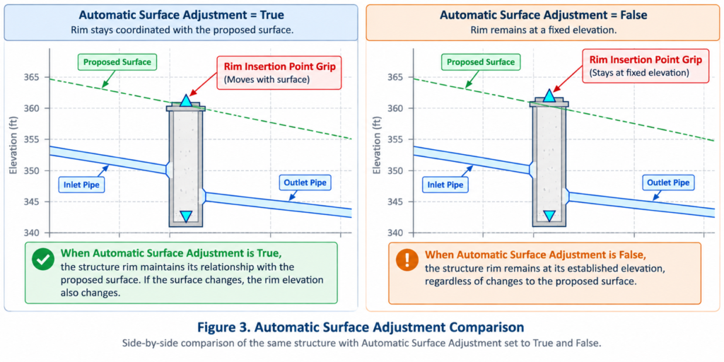
The distinction is important:
Automatic Surface Adjustment = True
The structure maintains a surface-based relationship.
Automatic Surface Adjustment = False
The structure can maintain its established vertical position independently of automatic surface adjustment.
Before dragging the rim grip, check this setting. Otherwise, the resulting elevation may not behave as expected.
- The Sump Grip: Depth or Elevation?
The second structure grip is located near the bottom of the structure.
This is the Sump grip.
The sump is the portion of the structure below the applicable pipe invert, but Civil 3D can control it in two different ways:
Control Sump By Depth
Control Sump By Elevation
This difference is extremely important when editing drainage structures.
Control Sump By Depth
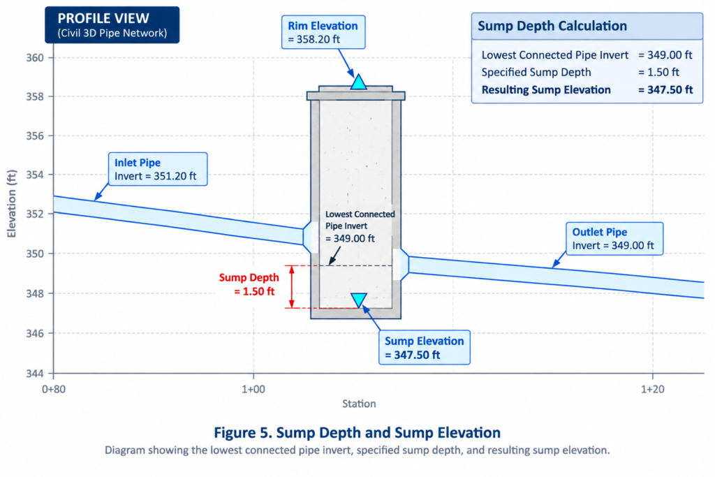
When the structure is set to Control Sump By Depth, the sump is controlled using a depth value.
The depth represents the vertical distance associated with the sump relative to the applicable connected pipe elevation.
For example, suppose the structure has a sump depth of 1.00 ft below the controlling pipe invert.
If the pipe network elevation changes, the resulting sump elevation can change as well because the sump is being defined by a depth relationship, rather than simply by one fixed elevation.
This approach is useful when your design requires a consistent sump depth below the connected pipe network.
Example
Suppose:
Lowest connected pipe invert = 350.00 ft
Required sump depth = 1.50 ft
Then the sump would be:
350.00 − 1.50 = 348.50 ft
If the controlling pipe invert later changes to 351.00 ft, a depth-controlled sump can maintain the 1.50-ft relationship.
That is the major advantage of controlling the sump by depth.
Why Sump Depth Matters in Drainage Design
A sump is not just a graphical extension below a structure.
Its depth can affect:
Structure excavation
Structure construction depth
Sediment collection
Pipe-to-structure relationships
Overall drainage network elevations
For networks designed using standard structure rules, controlling sump by depth can provide a consistent relationship across multiple structures.
Control Sump By Elevation
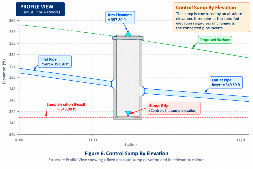
The second option is Control Sump By Elevation.
Instead of defining the sump as a depth below another elevation, you specify an absolute elevation.
For example:
Sump Elevation = 348.50 ft
The sump is therefore controlled by that elevation rather than by a specified depth.
This can be particularly useful for existing structures or structures where the sump elevation is based on surveyed or established field information.
Depth vs. Elevation
The easiest way to remember the difference is:
Sump by Depth = relative control
Sump by Elevation = absolute control
If your design intent is “keep the sump 1.5 ft below the controlling pipe,” think depth.
If your design intent is “the sump must remain at elevation 348.50 ft,” think elevation.
Editing Pipes in Profile View
Structures are only one part of the equation.
Civil 3D also allows you to edit the vertical geometry of pipes directly in Profile View.
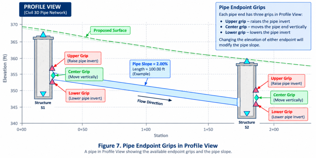
When a pipe is selected, grips appear at its endpoints.
These grips allow you to modify the elevation of the pipe endpoints and, consequently, the pipe’s slope.
This is one of the most useful techniques when developing a gravity drainage network.
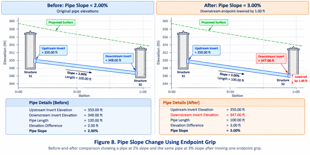
How Moving One Pipe Endpoint Changes Its Slope
A pipe’s slope is determined by the difference in elevation between its endpoints and the horizontal pipe length.
The basic relationship is:
$$ Slope = \frac{Elevation\ Difference}{Horizontal\ Length} $$
For example:
Pipe length = 100 ft
Upstream invert = 350.00 ft
Downstream invert = 348.00 ft
The elevation difference is:
$$ 350.00 – 348.00 = 2.00\ ft $$
Therefore:
$$ Slope = \frac{2.00}{100} = 0.02 $$
or:
2.00% slope
Now move the downstream endpoint 1 ft lower:
Upstream invert = 350.00 ft
Downstream invert = 347.00 ft
Length = 100 ft
The new slope becomes:
$$ \frac{350.00-347.00}{100}=0.03 $$
or:
3.00% slope
So, moving a single grip can completely change the vertical behavior of the pipe.
The Three-Grip Pipe Editing Concept
In Profile View, Civil 3D can display multiple grips associated with a pipe end.
These allow you to work with the pipe’s vertical geometry more interactively.
The endpoint grips are especially useful when you need to:
Raise an invert
Lower an invert
Adjust pipe slope
Coordinate a pipe with a structure
Resolve a vertical conflict
Improve drainage flow
Match a downstream connection
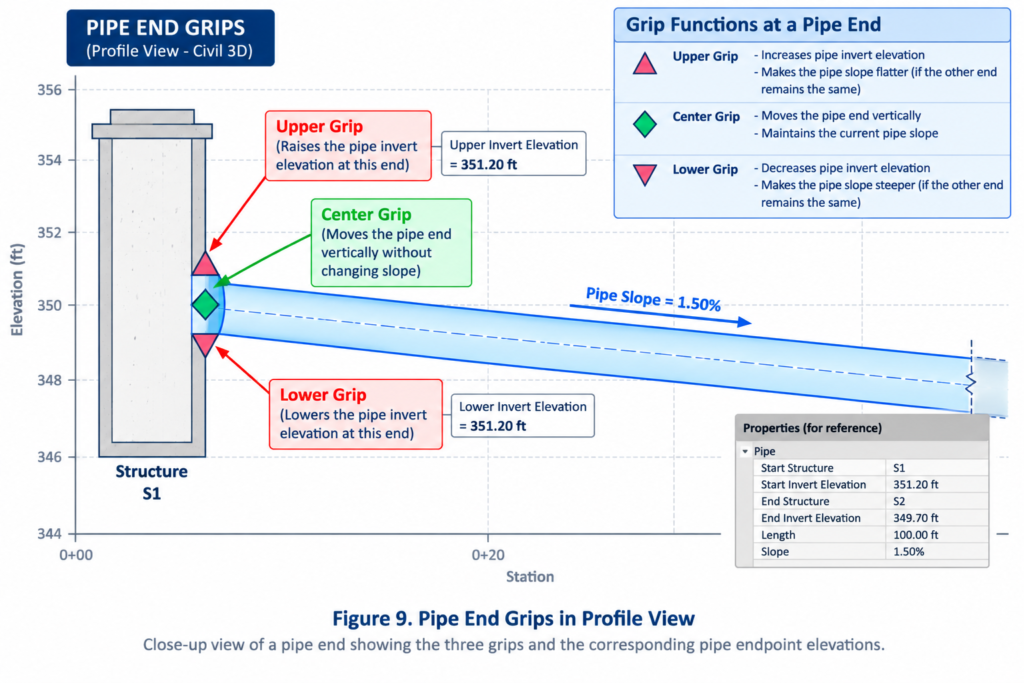
Rather than manually calculating every new elevation, you can use the Profile View to make the adjustment and then verify the resulting values.
A Practical Example: Fixing a Pipe Slope
Consider a storm sewer pipe connecting two structures.
The upstream structure has an outlet invert of:
352.00 ft
The downstream structure has an inlet invert of:
350.50 ft
The pipe is 100 ft long.
The slope is:
$$ \frac{352.00-350.50}{100}=0.015 $$
So the pipe has a:
1.50% slope
Suppose your design requires a steeper slope.
Instead of manually recalculating the entire pipe geometry, you can select the pipe in Profile View and adjust the appropriate endpoint grip.
After moving the grip, Civil 3D updates the pipe geometry.
You can then verify:
New invert elevation
New pipe slope
Structure connection
Pipe cover
Downstream network behavior
This is much faster than repeatedly switching between object properties and Profile View.
Profile View Is Where Pipe Network Problems Become Obvious
A pipe network can look perfectly organized in Plan View while having serious vertical problems.
For example, Plan View may show two pipes crossing each other without any obvious issue.
Profile View may reveal that:
The pipes occupy the same elevation.
One pipe has insufficient cover.
A pipe slope is too steep.
A pipe has an undesirable low point.
A structure is excessively deep.
The downstream connection is too high.
The sump is not deep enough.
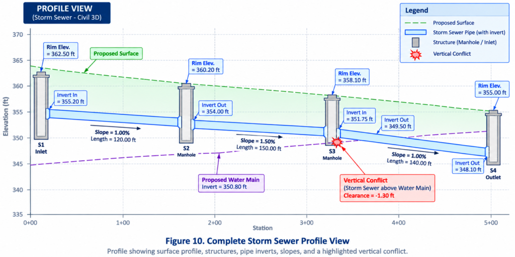
This is why Profile View should be treated as an active design environment—not simply a presentation drawing.
A Better Workflow for Editing Pipe Networks
Instead of randomly dragging grips, use a controlled workflow.
Step 1: Display the Pipe Network in Profile View
Make sure the relevant alignment, surface, pipes, and structures are displayed.
Step 2: Identify the Problem
Determine whether the issue is:
Rim elevation
Pipe invert
Pipe slope
Structure depth
Sump depth
Sump elevation
Surface coordination
Step 3: Check Object Properties
Before moving a grip, check the relevant structure or pipe properties.
For structures, pay particular attention to:
Automatic Surface Adjustment
Sump control method
Sump depth
Sump elevation
Step 4: Make the Graphical Adjustment
Use the appropriate grip to make the vertical adjustment.
Step 5: Verify the Result
After moving the grip, check the numerical values.
Don’t rely only on the visual position.
Step 6: Check Connected Components
This is the step many designers skip.
After changing one component, inspect the pipes and structures connected to it.
A small elevation adjustment at one structure can change the slope relationship of connected pipes.
When Should You Use Grips Instead of Properties?
Both methods have their place.
Use Grips When You Need to:
Quickly adjust elevations
Visually refine a profile
Change pipe slope
Adjust structure position
Resolve vertical conflicts
Coordinate pipes with a profile
Use Properties When You Need to:
Enter an exact elevation
Set a specific sump depth
Set an absolute sump elevation
Change Automatic Surface Adjustment
Verify object parameters
Review the current network configuration
A good Civil 3D workflow combines both approaches.
Grips are excellent for visual editing.
Properties are better for precise numerical control.
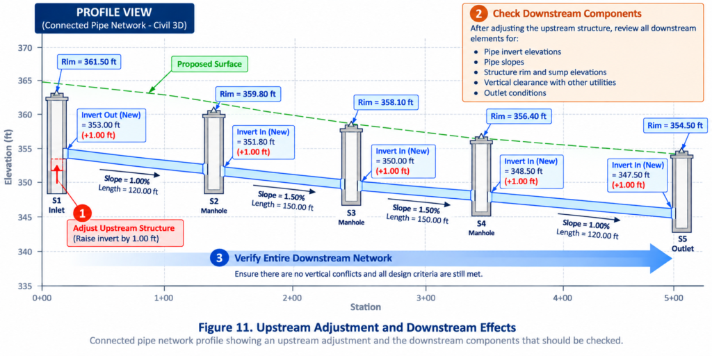
Important: Don’t Forget the Downstream Network
One of the biggest mistakes when editing pipe networks is looking only at the pipe or structure being changed.
Gravity drainage networks are interconnected.
If you lower one pipe endpoint, you may change:
Pipe slope
Downstream connection
Structure depth
Sump relationship
Cover
Hydraulic conditions
Therefore, after every significant vertical adjustment, follow the network downstream and check the resulting geometry.
Civil 3D Pipe Network Editing Checklist
Before finalizing your profile edits, check the following:
Structure rim elevations
Automatic Surface Adjustment settings
Pipe inlet elevations
Pipe outlet elevations
Pipe slopes
Structure insertion points
Sump control method
Sump depth
Sump elevation
Pipe cover
Structure depths
Upstream connections
Downstream connections
Proposed surface relationship
Applicable design criteria
Final Takeaway
The real advantage of Civil 3D pipe network profile grips is not simply that they make editing faster.
They allow you to see the relationship between the surface, structure elevations, pipe inverts, pipe slopes, and sumps while you are making changes.
The key concepts to remember are:
Rim Insertion Point grip → controls the vertical position of the structure insertion point.
Automatic Surface Adjustment → determines how the structure’s rim relates to the reference surface.
Sump grip → controls the sump according to the selected sump-control method.
Control Sump By Depth → maintains a depth-based relationship.
Control Sump By Elevation → uses an absolute elevation.
Pipe endpoint grips → allow vertical pipe adjustments and can change pipe slope.
Once these relationships are understood, Profile View becomes one of the most powerful places in Civil 3D to refine a pipe network.
The goal isn’t simply to move a grip until the profile looks right.
The goal is to understand what that grip is controlling—and what else in the network may change as a result.Editing a pipe network in Civil 3D becomes much faster when you work directly in Profile View.
Instead of opening the properties of every pipe and structure, Civil 3D provides dedicated grips that let you make vertical adjustments visually. However, these grips do more than simply move objects up and down. Their behavior depends on the properties of the pipe or structure being edited.
For structures, the two most important grips are the Rim Insertion Point grip and the Sump grip. Pipes have grips at their endpoints that can be used to modify their vertical geometry and slope.
Understanding what each grip controls is the key to editing pipe networks without creating unexpected elevations or slopes.
Structure Grips in Profile View
When you select a structure in Profile View, Civil 3D displays two primary grips.
Rim Insertion Point grip
Sump grip
The upper grip controls the vertical position of the structure insertion point, while the lower grip controls the sump.
[FIGURE 1 HERE]
These grips should not be treated as simple “move up/move down” controls. What happens when you move them depends on the structure properties.
- Editing the Structure Rim with the Rim Insertion Point Grip
The Rim Insertion Point grip is the upper grip displayed on the structure.
Dragging this grip vertically changes the structure’s insertion point elevation.
The important question is:
What happens to the rim when you move this grip?
The answer depends largely on the Automatic Surface Adjustment setting.
Automatic Surface Adjustment = True
When Automatic Surface Adjustment is set to True, the structure maintains its relationship with the selected reference surface.
This is particularly useful when structure rims need to follow a proposed finished surface.
For example, imagine a storm sewer manhole located beneath a roadway. If the roadway profile changes, you may want the manhole rim to remain coordinated with the finished grade rather than becoming disconnected from the surface.
With Automatic Surface Adjustment enabled, changing the Rim Insertion Point can also change the surface adjustment associated with the structure.
[FIGURE 2 HERE ]
When should you use this?
Automatic Surface Adjustment can be useful when:
Structure rims should follow finished grade.
The proposed surface is still being developed.
Roadway profile elevations are changing frequently.
Drainage structures are tied directly to the roadway surface.
You want the pipe network to remain coordinated with the surface.
This can save considerable time on projects where roadway and drainage profiles are being revised together.
- Automatic Surface Adjustment = False
When Automatic Surface Adjustment is set to False, the structure’s rim is not automatically maintained relative to the reference surface.
The structure can instead be controlled using its established elevation.
This is useful when you need a specific rim elevation or when the structure has an established elevation that should not automatically change with the surface.
[FIGURE 3 HERE]
The distinction is important:
Automatic Surface Adjustment = True
The structure maintains a surface-based relationship.
Automatic Surface Adjustment = False
The structure can maintain its established vertical position independently of automatic surface adjustment.
Before dragging the rim grip, check this setting. Otherwise, the resulting elevation may not behave as expected.
- The Sump Grip: Depth or Elevation?
The second structure grip is located near the bottom of the structure.
This is the Sump grip.
The sump is the portion of the structure below the applicable pipe invert, but Civil 3D can control it in two different ways:
Control Sump By Depth
Control Sump By Elevation
This difference is extremely important when editing drainage structures.
[FIGURE 4 HERE]
Control Sump By Depth
When the structure is set to Control Sump By Depth, the sump is controlled using a depth value.
The depth represents the vertical distance associated with the sump relative to the applicable connected pipe elevation.
For example, suppose the structure has a sump depth of 1.00 ft below the controlling pipe invert.
If the pipe network elevation changes, the resulting sump elevation can change as well because the sump is being defined by a depth relationship, rather than simply by one fixed elevation.
This approach is useful when your design requires a consistent sump depth below the connected pipe network.
Example
Suppose:
Lowest connected pipe invert = 350.00 ft
Required sump depth = 1.50 ft
Then the sump would be:
350.00 − 1.50 = 348.50 ft
If the controlling pipe invert later changes to 351.00 ft, a depth-controlled sump can maintain the 1.50-ft relationship.
That is the major advantage of controlling the sump by depth.
Why Sump Depth Matters in Drainage Design
A sump is not just a graphical extension below a structure.
Its depth can affect:
Structure excavation
Structure construction depth
Sediment collection
Pipe-to-structure relationships
Overall drainage network elevations
For networks designed using standard structure rules, controlling sump by depth can provide a consistent relationship across multiple structures.
[FIGURE 5 HERE]
Control Sump By Elevation
The second option is Control Sump By Elevation.
Instead of defining the sump as a depth below another elevation, you specify an absolute elevation.
For example:
Sump Elevation = 348.50 ft
The sump is therefore controlled by that elevation rather than by a specified depth.
This can be particularly useful for existing structures or structures where the sump elevation is based on surveyed or established field information.
[FIGURE 6 HERE]
Depth vs. Elevation
The easiest way to remember the difference is:
Sump by Depth = relative control
Sump by Elevation = absolute control
If your design intent is “keep the sump 1.5 ft below the controlling pipe,” think depth.
If your design intent is “the sump must remain at elevation 348.50 ft,” think elevation.
Editing Pipes in Profile View
Structures are only one part of the equation.
Civil 3D also allows you to edit the vertical geometry of pipes directly in Profile View.
When a pipe is selected, grips appear at its endpoints.
These grips allow you to modify the elevation of the pipe endpoints and, consequently, the pipe’s slope.
[FIGURE 7 HERE]
This is one of the most useful techniques when developing a gravity drainage network.
How Moving One Pipe Endpoint Changes Its Slope
A pipe’s slope is determined by the difference in elevation between its endpoints and the horizontal pipe length.
The basic relationship is:
$$ Slope = \frac{Elevation\ Difference}{Horizontal\ Length} $$
For example:
Pipe length = 100 ft
Upstream invert = 350.00 ft
Downstream invert = 348.00 ft
The elevation difference is:
$$ 350.00 – 348.00 = 2.00\ ft $$
Therefore:
$$ Slope = \frac{2.00}{100} = 0.02 $$
or:
2.00% slope
Now move the downstream endpoint 1 ft lower:
Upstream invert = 350.00 ft
Downstream invert = 347.00 ft
Length = 100 ft
The new slope becomes:
$$ \frac{350.00-347.00}{100}=0.03 $$
or:
3.00% slope
So, moving a single grip can completely change the vertical behavior of the pipe.
[FIGURE 8 HERE]
The Three-Grip Pipe Editing Concept
In Profile View, Civil 3D can display multiple grips associated with a pipe end.
These allow you to work with the pipe’s vertical geometry more interactively.
The endpoint grips are especially useful when you need to:
Raise an invert
Lower an invert
Adjust pipe slope
Coordinate a pipe with a structure
Resolve a vertical conflict
Improve drainage flow
Match a downstream connection
[FIGURE 9 HERE]
Rather than manually calculating every new elevation, you can use the Profile View to make the adjustment and then verify the resulting values.
A Practical Example: Fixing a Pipe Slope
Consider a storm sewer pipe connecting two structures.
The upstream structure has an outlet invert of:
352.00 ft
The downstream structure has an inlet invert of:
350.50 ft
The pipe is 100 ft long.
The slope is:
$$ \frac{352.00-350.50}{100}=0.015 $$
So the pipe has a:
1.50% slope
Suppose your design requires a steeper slope.
Instead of manually recalculating the entire pipe geometry, you can select the pipe in Profile View and adjust the appropriate endpoint grip.
After moving the grip, Civil 3D updates the pipe geometry.
You can then verify:
New invert elevation
New pipe slope
Structure connection
Pipe cover
Downstream network behavior
This is much faster than repeatedly switching between object properties and Profile View.
Profile View Is Where Pipe Network Problems Become Obvious
A pipe network can look perfectly organized in Plan View while having serious vertical problems.
For example, Plan View may show two pipes crossing each other without any obvious issue.
Profile View may reveal that:
The pipes occupy the same elevation.
One pipe has insufficient cover.
A pipe slope is too steep.
A pipe has an undesirable low point.
A structure is excessively deep.
The downstream connection is too high.
The sump is not deep enough.
[FIGURE 10 HERE]
This is why Profile View should be treated as an active design environment—not simply a presentation drawing.
A Better Workflow for Editing Pipe Networks
Instead of randomly dragging grips, use a controlled workflow.
Step 1: Display the Pipe Network in Profile View
Make sure the relevant alignment, surface, pipes, and structures are displayed.
Step 2: Identify the Problem
Determine whether the issue is:
Rim elevation
Pipe invert
Pipe slope
Structure depth
Sump depth
Sump elevation
Surface coordination
Step 3: Check Object Properties
Before moving a grip, check the relevant structure or pipe properties.
For structures, pay particular attention to:
Automatic Surface Adjustment
Sump control method
Sump depth
Sump elevation
Step 4: Make the Graphical Adjustment
Use the appropriate grip to make the vertical adjustment.
Step 5: Verify the Result
After moving the grip, check the numerical values.
Don’t rely only on the visual position.
Step 6: Check Connected Components
This is the step many designers skip.
After changing one component, inspect the pipes and structures connected to it.
A small elevation adjustment at one structure can change the slope relationship of connected pipes.
When Should You Use Grips Instead of Properties?
Both methods have their place.
Use Grips When You Need to:
Quickly adjust elevations
Visually refine a profile
Change pipe slope
Adjust structure position
Resolve vertical conflicts
Coordinate pipes with a profile
Use Properties When You Need to:
Enter an exact elevation
Set a specific sump depth
Set an absolute sump elevation
Change Automatic Surface Adjustment
Verify object parameters
Review the current network configuration
A good Civil 3D workflow combines both approaches.
Grips are excellent for visual editing.
Properties are better for precise numerical control.
Important: Don’t Forget the Downstream Network
One of the biggest mistakes when editing pipe networks is looking only at the pipe or structure being changed.
Gravity drainage networks are interconnected.
If you lower one pipe endpoint, you may change:
Pipe slope
Downstream connection
Structure depth
Sump relationship
Cover
Hydraulic conditions
Therefore, after every significant vertical adjustment, follow the network downstream and check the resulting geometry.
[FIGURE 11 HERE]
Civil 3D Pipe Network Editing Checklist
Before finalizing your profile edits, check the following:
Structure rim elevations
Automatic Surface Adjustment settings
Pipe inlet elevations
Pipe outlet elevations
Pipe slopes
Structure insertion points
Sump control method
Sump depth
Sump elevation
Pipe cover
Structure depths
Upstream connections
Downstream connections
Proposed surface relationship
Applicable design criteria
Final Takeaway
The real advantage of Civil 3D pipe network profile grips is not simply that they make editing faster.
They allow you to see the relationship between the surface, structure elevations, pipe inverts, pipe slopes, and sumps while you are making changes.
The key concepts to remember are:
Rim Insertion Point grip → controls the vertical position of the structure insertion point.
Automatic Surface Adjustment → determines how the structure’s rim relates to the reference surface.
Sump grip → controls the sump according to the selected sump-control method.
Control Sump By Depth → maintains a depth-based relationship.
Control Sump By Elevation → uses an absolute elevation.
Pipe endpoint grips → allow vertical pipe adjustments and can change pipe slope.
Once these relationships are understood, Profile View becomes one of the most powerful places in Civil 3D to refine a pipe network.
The goal isn’t simply to move a grip until the profile looks right.
The goal is to understand what that grip is controlling—and what else in the network may change as a result.