
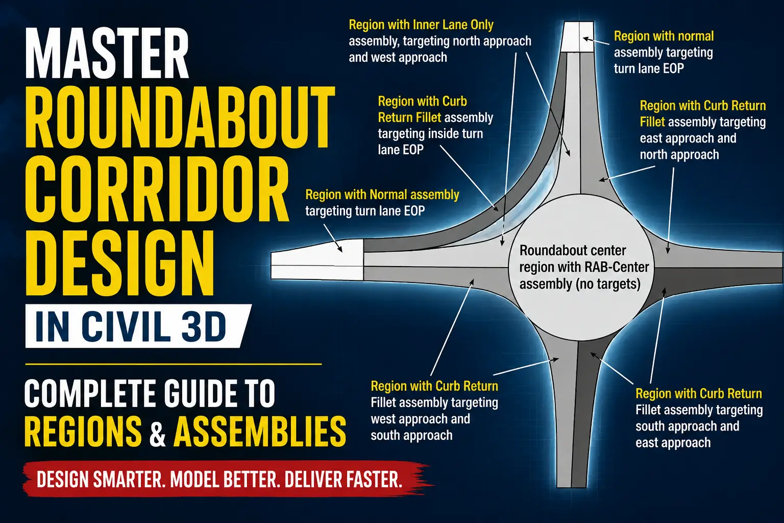
Roundabout Corridor Regions & Assemblies in Civil 3D
Designing a roundabout in Autodesk Civil 3D is a specialized task that differs significantly from modeling standard roadways. Unlike straight alignments, roundabouts require multiple targeted assemblies, carefully defined corridor regions, and smooth transitions between approaches, curb returns, and the central island.
In this comprehensive guide, Civil Designs explore the full workflow for creating Civil 3D roundabout corridor regions, including which assemblies to use for each zone and best practices for professional modeling.
Why Roundabout Corridors Require Multiple Regions
A roundabout contains several distinct geometric zones, each with unique grading and targeting requirements:
- Entry lanes
- Exit lanes
- Circulatory roadway
- Splitter islands
- Curb return fillets
- Central island
- Transition tapers
Using a single assembly for the entire roundabout can lead to issues such as:
- Incorrect curb grading
- Broken daylight lines
- Corridor targeting failures
- Poor pavement transitions
- Surface triangulation issues
Professional roundabout design in Civil 3D relies on creating multiple corridor regions to manage these complexities effectively.
Typical Roundabout Regions in Civil 3D
Professional roundabout workflows break the corridor into regions, each using assemblies optimized for its geometry.
1. Normal Roadway Assembly Region
This region covers standard roadway approaches before the roundabout influence zone.
Common Assembly Components:
- Lane
- Shoulder
- Curb & gutter
- Sidewalk
- Daylight subassemblies
Purpose: Targets standard edge-of-pavement (EOP) alignments.
Best Practice: Keep this region separate from curb return regions to prevent transition conflicts.
also check our post about how How Autodesk Forma is Revolutionizing 3d workflow.
2. Inner Lane Only Assembly Region
As vehicles enter the roundabout, lane configurations change. Outer lanes often taper, and lane widths vary.
Common Uses:
- Single-lane transitions
- Entry narrowing
- Lane merge areas
Benefits:
- Cleaner corridor targeting
- Better pavement edge control
- Reduced overlap errors
3. Curb Return Fillet Assembly Region
Curb return areas connect approaches, circulatory lanes, and exit geometry. Rapid offset changes and slope transitions make this region highly sensitive.
Typical Targets:
- Inside EOP
- Outside EOP
- Curb return alignments
- Feature lines
Why Separate Regions Matter:
- Maintains smooth grading
- Prevents corridor bowties
- Improves curb flow
- Simplifies surface cleanup
4. Roundabout Center Region
The central island often uses a unique assembly.
Typical Components:
- Raised curb
- Mountable apron
- Landscaping zone
- Central island grading
Important Note: Many workflows rely on fixed geometry, feature lines, and manual grading controls, rather than standard corridor targets.
Corridor Targeting Strategy for Roundabouts
Corridor targeting is crucial for successful roundabout modeling. Each region may require different target objects:
| Region | Common Targets |
|---|---|
| Normal roadway | EOP alignments |
| Entry transition | Offset alignments |
| Curb return | Feature lines |
| Center island | Fixed widths |
| Exit lanes | Dynamic offsets |
Incorrect targeting can cause corridor gaps, spikes, daylight failures, and triangulation errors.
Recommended Workflow for Roundabout Corridors
Step 1 — Create Separate Alignments
- Approach alignments
- Curb return alignments
- Circulatory alignment
Step 2 — Build Multiple Assemblies
- Avoid using one assembly everywhere
- Create assemblies for roadway approaches, curb returns, lane transitions, and center islands
Step 3 — Divide Corridor into Regions
- Split at lane transitions, curb returns, entry/exit points, and central circulation zones
Step 4 — Apply Proper Targets
- Assign feature lines, offset alignments, profiles, and daylight targets to each region
Step 5 — Rebuild & Clean Corridor Surfaces
- Inspect triangulation
- Remove crossing links
- Clean corridor boundaries
- Verify grading continuity
Common Mistakes in Civil 3D Roundabout Design
- Using one assembly everywhere
- Poor region break placement
- Incorrect target assignments
- Ignoring feature lines
Feature lines are essential for controlling curb flow, grading transitions, and island shaping.
Best Practices for Professional Roundabout Modeling
- Use dedicated assemblies for each geometric condition
- Minimize complex targets in a single region
- Use feature lines strategically, especially around splitter islands and curb returns
- Keep region limits logical, splitting where geometry behavior changes
Final Thoughts
Professional roundabout design in Civil 3D depends on understanding corridor regions and assemblies. By dividing the roundabout into multiple, targeted regions—normal roadway sections, curb return fillets, inner lane transitions, and central island zones—you achieve:
- Cleaner grading
- Smoother surfaces
- Better constructability
- Easier corridor management
Mastering roundabout corridor regions will dramatically improve your Civil 3D workflow, efficiency, and model quality.
Need Help With Civil 3D Roundabout Modeling?
At Civil 3D Pro we specialize in:
- Roundabout corridor modeling
- Transportation design drafting
- Corridor targeting workflows
- Grading optimization
- Civil 3D training & support
Stay connected for more advanced Civil 3D tutorials and transportation engineering workflows.


One Comment