Modeling a Cul-de-Sac Corridor in AutoCAD Civil 3D Using Multiple Baselines and Assemblies
Modeling a Cul-de-Sac Corridor in AutoCAD Civil 3D Using Multiple Baselines and Assemblies
Introduction
Cul-de-sac roads are a common feature in residential developments, but modeling them accurately in AutoCAD Civil 3D can be challenging. Unlike straight or simple curved roads, a cul-de-sac requires multiple baselines, carefully managed assemblies, and proper crown control to achieve a clean and constructible corridor model.
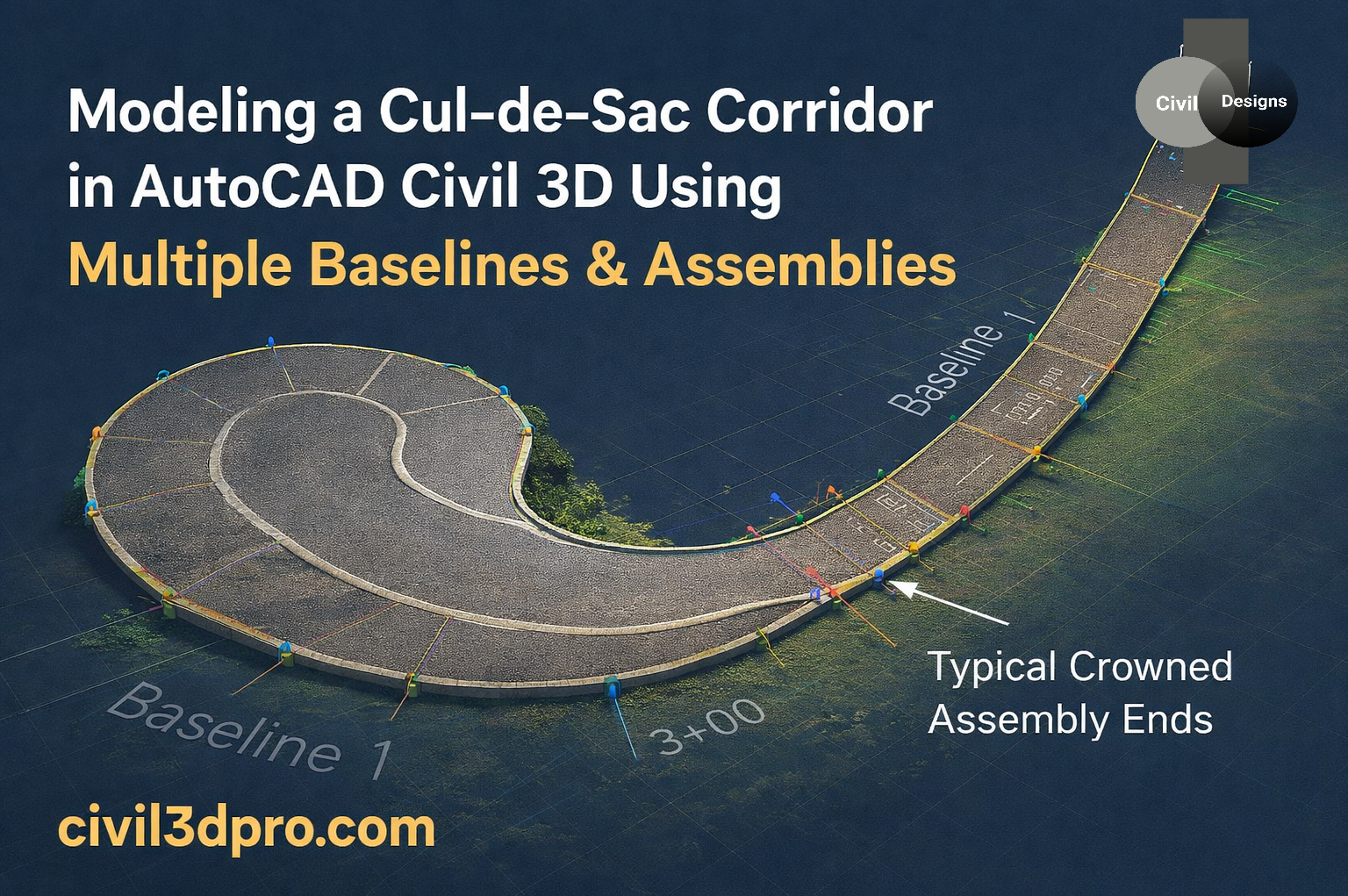
In this post, we’ll look at how Baselines and Assemblies, work together to create a smooth and accurate cul-de-sac corridor, similar to the example shown in the figure above.
Understanding the Corridor Baseline Setup
To model a cul-de-sac efficiently, Civil 3D typically uses more than one baseline. Each baseline controls a different portion of the road so that geometry and cross-sections behave correctly.
Baseline 1 – Main Road Alignment
Baseline 1 represents the main road alignment leading into the cul-de-sac. It:
– Controls the primary roadway geometry
– Maintains consistent cross-sections as the road approaches the cul-de-sac
– Uses standard road assemblies for typical sections along the approach road
This keeps the main corridor simple, stable, and easy to edit when changes are needed along the straight or curved approach.
Baseline 2 – Circular Bulb / Turning Area
Baseline 2 is used for the circular bulb or turning area of the cul-de-sac. Because the geometry changes rapidly in this region, using a separate baseline gives you much better control over:
– Lane widths
– Slopes and crossfalls
– Transitions between the approach road and the circular end
Using multiple baselines ensures that each part of the road behaves correctly, without forcing a single alignment to handle all the complexity.
Assembly Placement and Transition
Assemblies are assigned along each baseline based on station ranges and the functional requirements of that portion of the road.
– Standard road assemblies are applied along the straight or curved approach road (Baseline 1).
– Specialized cul-de-sac assemblies are applied along the circular portion (Baseline 2).
At the junction between Baseline 1 and Baseline 2, Civil 3D manages a smooth transition by:
– Matching target surfaces
– Aligning lane widths
– Maintaining proper slopes and offsets
When this transition is handled correctly, it prevents:
– Surface breaks
– Overlapping links
– Distorted or twisted corridor shapes
The result is a corridor that looks clean in both plan and model views, and behaves correctly when you create surfaces and calculate quantities.
—
Typical Crowned Assembly Ends
A key detail in cul-de-sac design is the Typical Crowned Assembly Ends.
Crowned assemblies are essential because they:
– Preserve the road crown for proper drainage
– Ensure left and right lanes meet correctly at the centerline
– Help avoid surface twisting, especially in tight curves and turning areas
Properly terminating crowned assemblies at the transition zone between the main road and the circular bulb:
– Keeps the corridor surface smooth
– Prevents unwanted kinks or flat spots
– Supports more accurate volume and earthwork calculations
Why This Method Matters
Using multiple baselines and correctly managed assemblies provides several practical advantages in AutoCAD Civil 3D:
✔ Cleaner, more stable corridor surfaces
✔ More accurate earthwork quantities
✔ Better drainage behavior due to controlled crown and slopes
✔ Fewer corridor errors, warnings, and rebuild issues
✔ More professional, construction-ready models
This approach is especially valuable for:
– Subdivision design
– Residential streets
– Local road and small cul-de-sac projects
By investing a bit of extra effort in setting up multiple baselines and appropriate assemblies, you can save time later on, reduce troubleshooting, and deliver higher-quality designs that are easier for construction teams to build in the field.
Conclusion
Modeling a cul-de-sac corridor in AutoCAD Civil 3D becomes much more straightforward when you understand how to use multiple baselines, station-controlled assemblies, and proper crown handling. The method shown above reflects industry best practices and helps you produce reliable, high-quality roadway designs.
If you want more Civil 3D tutorials, tips, and real-world workflows, keep exploring [www.civil3dpro.com]— where practical design meets professional results.