Understanding Grading
Grading refers to the process of shaping land for construction or design purposes. From a design standpoint, it differs from corridor design, which also modifies terrain but is primarily used for long, consistent, linear features like roads and channels. Grading typically applies to smaller areas or features that are not continuous or uniform.
The result of a grading design is a surface—just like the surface used to represent existing terrain in Chapter 4, “Modeling the Existing Terrain Using Surfaces.” To build a surface for existing ground (EG) elevations, breaklines are drawn along key linear features such as curbs and ditches. In Civil 3D 2025, you can generate these breaklines using survey data. For a design surface, you similarly draw breaklines along the proposed curbs and ditch lines. The process mirrors that of creating an EG surface, but now the features represent planned construction elements. For example, in Figure 17.1, the pond grading is shown using red and blue contours. Civil 3D 2025 tools helped define the pond’s edges based on design parameters like depth, shape, and size, and these edges were then used to create the final pond surface.

Understanding Feature Lines
In Chapter 4, survey figures were used as breaklines in the EG surface. For a design surface, feature lines are commonly used to define most breaklines. Both survey figures and feature lines are 3D linear objects that can be named, styled, and displayed in the Prospector. The key difference is that feature lines are created as part of the design, while survey figures come from field-collected data.
Understanding Sites
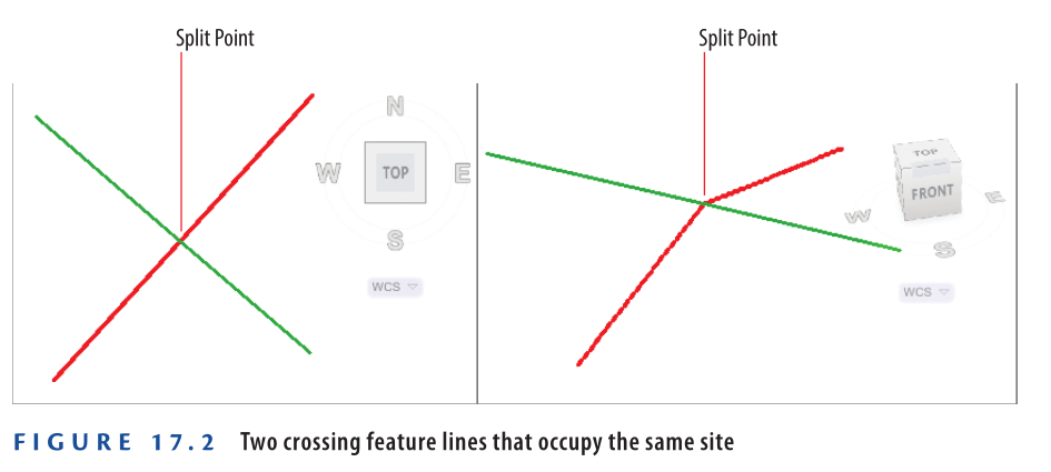
When using feature lines, the concept of sites becomes important. Feature lines within the same site are aware of each other and will interact when they cross. For example, if two feature lines intersect within the same site, one will adjust its elevation to match the other at the intersection point, creating what’s known as a split point. If such interaction is not desired, each feature line can be placed in a separate site. Figure 17.2 illustrates this behavior in both plan and 3D views, showing how the red feature line bends to match the green one at the split point because they belong to the same site in Civil 3D 2025.
Understanding Feature-Line Geometry
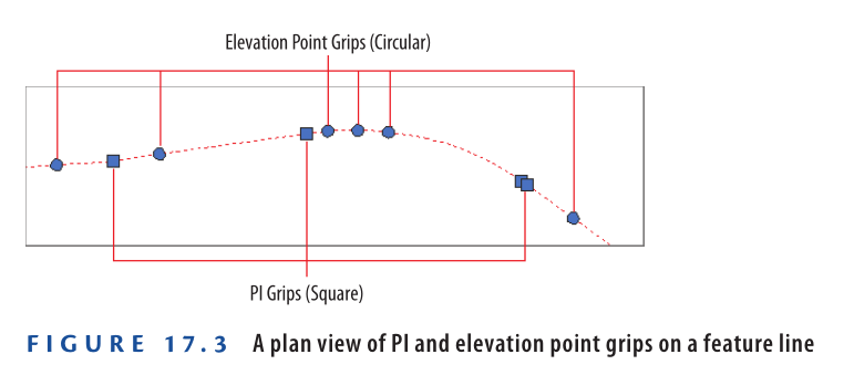
Feature lines in Civil 3D 2025 are defined by two types of points: PIs and elevation points. PIs (Points of Intersection) are shown as square grips and can be adjusted in all three dimensions. Elevation points, shown as circular grips, have limited editing—only their elevation can be changed, while their plan location remains fixed along the feature-line path defined by the PIs. Figure 17.3 illustrates both grip types on a single feature line. This limited movement is useful because it allows you to add multiple elevation points along a simple plan shape, like a rectangle, without altering the overall geometry.
Creating Feature Lines
Civil 3D 2025 offers a full range of tools for creating feature lines. You can draw them from scratch, convert AutoCAD® polylines, or extract them from Civil 3D objects like corridors or profiles. When drawing manually, you must specify the elevation of each PI. For other methods, elevations are taken from the source object.
Exercise 17.1: Create Feature Lines
In this exercise, you’ll create feature lines for a lot boundary and a building pad within the lot. You’ll use a corridor, draw one manually, and create one from existing objects.
- Open Creating Feature Lines.dwg which you can download from Video tutorial description below. This file focuses on lot 25 in the top-right and bottom-right viewports. The corridor layer is visible.
- Go to the Home tab → Feature Line ➢ Create Feature Line From Corridor.
- In either viewport, click the front edge of the corridor at lot 25.
- In the Create Feature Line From Corridor dialog box, set Site to Lot Grading, Style to Lot Grading – ROW, then click OK. A red feature line appears.
- Press Esc. On the Home tab, click Feature Line ➢ Create Feature Line.
- In the Create Feature Lines dialog, choose Style: Lot Grading, then click OK. Use Center snap to select the center of the red circle at the north corner of lot 25.
- When prompted for elevation, press Enter. For the next point, use Endpoint snap to click the west corner of lot 25.
- On the command line, click Surface to select a surface.
- Choose EG in the Select Surface dialog, then click OK. The elevation appears as 190.059 (57.930).
- Press Enter to accept the elevation.
- Click Arc → then Secondpnt on the command line.
- Use Nearest snap to pick a point along the back lot line.
- Use Endpoint snap to click the south corner of lot 25.
- Click SUrface, then press Enter to accept elevation 190.456 (58.027).
- Click Line, then use Center snap to click the circle at the east corner of lot 25.
- Press Enter, then Esc to finish. You’ve created a feature line matching the corridor edge and back lot elevations.
- On the Home tab, click Feature Line ➢ Create Feature Lines From Objects. Select the rectangle at the center of lot 25, press Enter.
- In the Create Feature Lines dialog, check Style and set it to Lot Grading, then click OK.
The new feature line appears at elevation 0. Zoom out to view the blue rectangle near the lot label and parcel lines. - Save and close the drawing.
To check results, open Creating Feature Lines – Complete.dwg.
https://www.mediafire.com/file/krcvplu8ktzt2uu/Creating+Feature+Lines+-+Complete.dwg/file
Watch Complete Video Tutorial here for this Exercise:
Editing Feature Lines
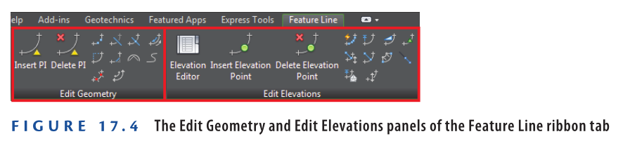
Civil 3D 2025 includes powerful editing tools for feature lines. These are found on the Feature Line ribbon tab under two panels: Edit Geometry and Edit Elevations (see Figure 17.4).
Using Edit Geometry Commands
AutoCAD Civil 3D 2025 offers a robust set of geometry-editing commands specifically designed for feature lines. These commands are accessible on the Edit Geometry panel of the Feature Line ribbon tab and include:
- Insert PI – Adds a new Point of Intersection (PI) at a user-defined location. The PI can be modified in 3D.
- Delete PI – Removes one or more PIs from a selected feature line.
- Break – Divides a feature line into two segments. You can either insert a gap or break it end-to-end.
- Trim – Trims a feature line so that it terminates precisely at another object.
- Join – Combines multiple feature lines into one, provided any gaps between them fall within the acceptable tolerance.
- Reverse – Switches the start and end points of the feature line, also reversing station direction. This can impact labels and editing functions.
- Edit Curve – Modifies the radius of an existing curve within the feature line.
- Fillet – Adds a curve at a PI, with radius settings and the option to apply it to multiple PIs at once.
- Fit Curve – Replaces multiple line segments with an arc, helping simplify the geometry. Unlike Smooth, Fit Curve allows manual control of curve placement and produces static arcs.
- Smooth – Converts all PIs into dynamic curves that maintain tangency as the feature line is edited.
- Weed – Reduces unnecessary vertices by automatically removing those based on angle or distance criteria.
- Stepped Offset – Generates a parallel feature line with customizable elevation control.
Exercise 17.2: Edit Feature Lines with Geometry Commands
In this exercise, you’ll refine the feature line created in the previous activity and then combine it with another one.
- Open the drawing file named Editing Feature Line Geometry.dwg which you can download from video tutorial description below.
- Click on the green feature line. If the Edit Geometry panel is not shown, select Edit Geometry from the ribbon.
- Click Insert PI. Use the Center object snap to click the center of the blue circle.
- When asked for elevation, select the Surface option.
- Ensure the EG surface is selected and click OK, then press Enter to accept the suggested elevation.
- Next, use the Center object snap to click the red circle’s center.
- Again, select Surface for elevation and press Enter to use the surface value.
Now that PIs have been added, it’s time to include a missing curve.
- Press Esc twice to cancel the current command. Click on the green feature line and then choose Fit Curve from the ribbon.
- On the command line, select the Points option.
- Use the Center snap to select the blue circle center as the start point.
- Use Center again to select the red circle center. Press Esc twice to finish the command.
A curve now aligns with the back lot geometry. Next, you’ll break and join feature lines between lots 25 and 26.
- Select any feature line and click Break on the ribbon.
- Choose the blue perimeter feature line for lot 25.
- Select First point on the command line and use the Endpoint snap to click the corner shared by lots 25 and 26.
- Repeat the same step to confirm the second break point at the same corner. Press Esc twice to exit.
Even though there’s no visible change, the blue feature line has now been split.
- Select the blue feature line at the back of lot 25, then click Join.
- Click the green feature line, then press Esc twice to finish.
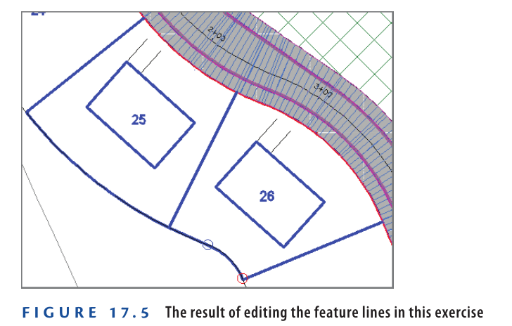
The feature lines are now merged into one, and the green line changes to blue to indicate this (see Figure 17.5).
- Save and close the drawing.
You can view the results of successfully completing this exercise by opening
Editing Feature Line Geometry – Complete.dwg.
https://www.mediafire.com/file/gsp24ufwaomzm8x/Editing+Feature+Line+Geometry+-+Complete.dwg/file
Watch Complete Video Tutorial here for this Exercise:
Using Edit Elevation Commands
The feature line elevation-editing commands provided by Civil 3D 2025 are as follows:
Elevation Editor: Opens the Grading Elevation Editor tab in Panorama, where you can view and edit all feature-line data at once.
Insert Elevation Point: Adds one or more elevation points to a feature line.
Delete Elevation Point: Removes elevation points from a feature line to simplify it.
Quick Elevation Edit: Allows interactive elevation and slope editing using tooltips to show values and directions.
Edit Elevations: Lets you modify individual points and segments via the command line.
Set Grade/Slope Between Points: Sets a constant grade between a start and endpoint by calculating in-between elevations.
Insert High/Low Elevation Point: Calculates a high or low point by projecting slopes from two selected points and creating a point at the intersection, useful for drainage design.
Raise/Lower By Reference: Adjusts all elevations of a feature line based on a reference point and an elevation difference.
Set Elevation By Reference: Sets elevations of specific points using a reference point and elevation difference.
Adjacent Elevations By Reference: Projects elevations from one feature line to another with an optional elevation difference, helpful for parallel lines like curbs or walls.
Grade Extension By Reference: Calculates elevation by extending a grade from another feature line.
Elevations From Surface: Projects a feature line onto a surface, optionally adding elevation points at triangle edge crossings to match terrain exactly.
Raise/Lower: Changes all elevations of a feature line at once using a specified elevation difference.
Exercise 17.3: Edit Feature Lines with Elevation Commands
In this exercise, you’ll use Civil 3D 2025 commands to set the Lot 25 building pad to the right elevation and adjust back-lot lines of Lots 25 and 26 to better fit existing ground.
- Open the drawing named Editing Feature Line Elevations.dwg which you can download from video tutorial description below.
- Click any feature line. If Edit Elevations panel isn’t visible, click Edit Elevations on the ribbon.
- Click Quick Elevation Edit. Hover the cursor over the north corner of Lot 25.
The tooltip should show an elevation of 189.297′ (57.695m). - Hover over each corner of Lot 25 and note the elevations.
The highest is the south corner: 190.456′ (58.027m). The building pad (blue rectangle) should be set slightly higher for proper drainage. - Press Esc twice to clear selection. Select the building pad feature line of Lot 25.
- On the ribbon, click Raise/Lower By Reference.
- When prompted, use Endpoint snap to hover over the south corner of Lot 25 without clicking.
- Check the coordinate readout. If the Z-value shows 0.0000, press Tab repeatedly until it shows 190.4564 (58.027).
This ensures the correct reference elevation is used from the feature line geometry, not the base parcel geometry.

- With the proper value shown in the coordinate readout, click the point to snap to it.
- When prompted to specify a point on the building pad feature line, click the south corner of the building pad feature line. When prompted to specify the grade, type 2 and press Enter.
If you watch the lower-right viewport carefully, you’ll see the feature line move upward to join the perimeter feature line. This places the building pad at an elevation that creates a 2 percent downward slope from the south corner of the building pad to the south corner of the lot. All the other slopes will be steeper because the other lot corners are lower than the south corner. - Press Esc to clear the previous selection. Click the feature line that represents the rear of the lots, and then click Elevations From Surface on the ribbon.
- In the Set Elevations From Surface dialog, verify that EG is selected and that the box next to Insert Intermediate Grade Break Points is checked. Click OK.
- At the command line, click Partial to invoke the Partial option. Select the feature line representing the rear of the lots.
- When prompted to specify the start point, click the west corner of Lot 25, and then click the south corner of Lot 26 to specify the endpoint.
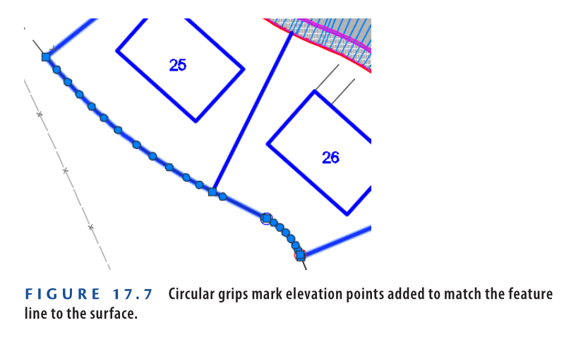
A series of green circle markers appears on the feature line. - Press Enter to complete the command.
A number of circular grips are now visible on the feature line (see Figure 17.7). These represent additional elevation points that were required for the feature line to match the surface precisely.
- Save and close the drawing.
You can view the results of successfully completing this exercise by opening
Editing Feature Line Elevations – Complete.dwg.
https://www.mediafire.com/file/92pd5uqigdhstw6/Editing+Feature+Line+Elevations+-+Complete.dwg/file
Watch Complete Video tutorial here for this Exercise:
Your Pad or Mine?
For land-development projects that involve buildings, it’s common for the contractor to prepare a flat area where the building will be placed. This is often referred to as the building pad. In a residential development such as the example in this book, a building pad is often prepared for each lot to accommodate the home that will be built.
Understanding Grading Objects
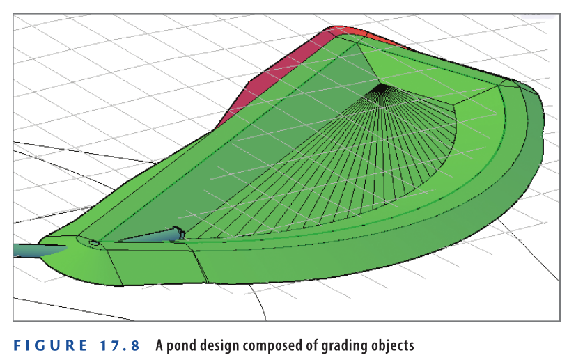
At times, you’ll want Civil 3D 2025 to calculate the location, shape, and elevations of feature lines rather than designing them yourself. Examples of this situation would be projecting a slope through a certain distance or elevation or finding the intersection of a slope with a surface. For these cases, Civil 3D 2025 provides the grading object. Figure 17.8 shows a pond design composed of several grading objects, each one using a different set of parameters to calculate an edge that defines the shape of the pond.
Understanding Grading Objects
A grading object is a collection of feature lines whose geometry, location, and elevation are calculated by Civil 3D 2025 based on design parameters that you have applied to a feature line. That’s quite a daunting definition, so here’s a look at it broken down into several parts:
▶ A grading object is a collection of feature lines (and other things not important to name at this time), so it behaves as one object. The feature lines in this collection have many of the same characteristics as individual feature lines as well as some unique characteristics that relate to being part of a grading object.
▶ Everything about a grading object is calculated by Civil 3D 2025. Very similar to the way Civil 3D calculates a corridor, grading objects can’t be edited directly, but they respond automatically when their design parameters are edited. This is a little different from an individual feature line, which you can grip-edit at will.
▶ You assign the design parameters to a feature line. To create a grading object, you start by picking a feature line in the drawing. The design parameters you provide, such as slope, distance, elevation, and so on, are projected from this feature line to create the resulting grading object. A feature line that serves as the basis for a grading object is called a baseline.
Understanding Grading Criteria
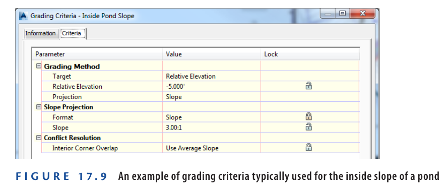
The design parameters you apply to a grading object can require multiple pieces of information. For this reason, Civil 3D 2025 utilizes a system of grading criteria, which enables you to refer to a set of instructions by name rather than having to re-specify them for each grading design. For example, you might have criteria with the name Curb, which instruct Civil 3D 2025 to project upward at a very steep slope for a very short distance. Similar criteria with names like Pond Embankment, Ditch Slope, and so on might be created alongside your Curb criteria. You can organize your named grading criteria even further by grouping them into grading criteria sets. For example, you might have one criteria set for pond grading, another for parking lots, another for athletic fields, and so on. Figure 17.9 shows grading criteria that would be used to create the inside slope of a pond.
Understanding Grading Groups
A grading group is a named collection of grading objects that enables you to perform certain important functions with multiple grading objects simultaneously. For example, you can create a surface from a grading group or calculate cut and fill values by comparing a grading group to a surface in the drawing.
Understanding Grading Objects and Sites
Like feature lines, grading objects must exist in a Civil 3D 2025 site. When two or more grading objects occupy the same site, there is potential for them to interact. There is also the potential for grading objects to interact with other feature lines in the same site. This interaction can benefit some designs, but there are cases where this interaction will cause the design to be incorrect. Therefore, it’s important to proactively manage sites while you’re working with grading objects and feature lines.
Creating Grading Objects
You begin creating a grading object by launching the Grading Creation Tools command. This opens the Grading Creation Tools toolbar (see Figure 17.10), which is similar to the Alignment Layout Tools and the Network Layout Tools toolbars that you used in previous chapters. Like those toolbars, the Grading Creation Tools toolbar provides the commands to configure your design, create new design objects, and edit those objects.

I thought Detention Was a Bad thing
The pond designed in this exercise is called a detention pond. Its purpose is to control stormwater release to match the pre-development flow rate. When it rains, runoff enters through inlets and flows to the pond via underground pipes. The pond outlet limits water flow, causing water to back up, which creates the need for the pond to hold it temporarily. After the storm ends, the water remains in the pond until it slowly drains.
Why is this important? Before development replaced natural surfaces like grass, soil, and forests with pavement, runoff left the area at a slower pace. Now, less water soaks into the ground, and runoff moves faster on paved surfaces. This increase in flow speed can cause erosion damage that needs to be controlled. Using a pond in the design is a common solution to reduce this risk.
Exercise 17.4: Create Grading objects
In this task, you will create a pond using grading objects.
- Open the drawing named Creating Grading Objects.dwg which you can download from video tutorial description below. The view is zoomed to the proposed location of the stormwater detention pond. You will start building the pond model with the green feature line marking the pond’s top inside edge.
- Go to the Home tab on the ribbon and select Grading → Grading Creation Tools.
- In the Grading Creation Tools toolbar, click Set The Grading Group. Choose Pond and click OK. In the Site dialog, select Pond and click OK.
- In the Create Grading Group dialog, enter Pond in the Name field. Confirm that Automatic Surface Creation is enabled, then click OK. Close the Create Surface dialog box by clicking OK.
- Expand the criteria list and select Grade To Relative Elevation, as shown in Figure 17.11.

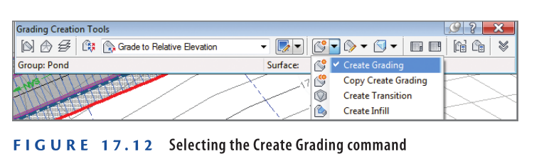
- Expand the list of creation commands, and click Create Grading, as shown in Figure 17.12.
- When asked to select a feature, click the green feature line. For the grading side, choose a point inside the feature line.
- Press Enter to apply grading along the entire length.
- For the relative elevation value, type -7 (-2.13), then press Enter. When asked for a format, press Enter to keep the default, Slope.
- When prompted for slope, enter 3 and press Enter to apply a 3:1 slope.
After a moment, a grading object forms representing the pond’s inside slope. A surface is also created and displayed with red and blue contours in plan view. - Expand the creation tools list and select Create Infill. Click near the pond’s center.
This infill is a special grading object that fills a void in the grading group. It doesn’t add elevation points but lets the grading surface cover open areas. Infill can be placed in any closed area formed by one or more feature lines on the same site. - Select the Grade To Distance criteria.
- Expand the creation tools, choose Create Grading. When prompted, click the same green feature line selected in step 7.
- For grading side, select a point outside the pond. Press Enter to apply grading for the full length.
- Press Enter to accept the default distance of 10.000′ (3.000m). When asked for a format, type G to select Grade and press Enter.
- Press Enter to accept the default 2% grade.
A new grading object forms, representing the pond berm. - On the Grading Creation Tools toolbar, click Set The Target Surface. In the Select Surface dialog, choose EG and click OK.
- Select the Grade To Surface criteria. Expand the creation tools list and pick Create Grading.
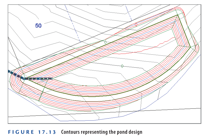
- Click the outside edge of the grading object from step 18. Press Enter at all prompts to keep defaults.
This produces a 3:1 daylight slope that meets the EG surface and finishes the pond surface, shown by the red and blue contours (see Figure 17.13).
- Save and close the drawing.
You can view the results of successfully completing this exercise by opening Creating Grading Objects – Complete.dwg.
https://www.mediafire.com/file/tc6w5xx28z8bfd3/Creating+Grading+Objects+-+Complete.dwg/file
Watch Complete Video Tutorial here for this Exercise:
Editing Grading objects
Due to the dynamic behavior of grading objects, editing a feature line that forms a grading-object baseline automatically updates the grading object. This makes editing grading objects straightforward. Additionally, two tools let you modify the grading criteria: Grading Editor and Edit Grading. The Grading Editor opens Panorama for table-format editing, while Edit Grading works through a command-line interface.
Exercise 17.5: Edit Grading objects
In this exercise, you will modify the pond grading objects created earlier.
- Open Editing Grading Objects.dwg which you can download from video Tutorial description below.
- Select the green feature line marking the pond berm’s inside edge. Click the grip at the northeast corner, then use the Center object snap to select the center of the red circle to the east. The grading object recalculates based on the updated baseline shape. The grading-group surface updates accordingly, adjusting contours to fit the new shape.
- With the feature line still selected, click Raise/Lower on the Edit Elevations panel of the ribbon. You will be prompted to specify an elevation difference.
- Enter -1 (-0.3) and press Enter to lower the feature line by 1′ (0.3m). The grading group and surface update. The pond bottom is now too low and must be raised.
- Press Esc to clear the feature line selection. On the Modify tab, click Grading.
- Choose Grading Editor, then click inside the pond’s inside embankment area. The grading edges highlight to help with selection.
- In the Grading Editor tab of Panorama, type -6 (-1.83) for Relative Elevation and press Enter. The grading group updates, raising the pond bottom by 1′ (0.3m).
- On the Grading tab, click Edit Grading. Click within the berm’s top area.
- When prompted for a distance, enter 12 (3.6) and press Enter.
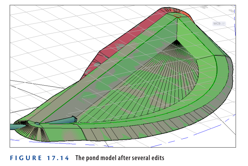
- Press Enter twice to accept previous settings, then press Enter a third time to finish the command.
The grading group and surface adjust to reflect the wider berm and the earlier shape and elevation changes (see Figure 17.14).
- Save and close the drawing.
You can view the results of successfully completing this exercise by opening Editing Grading Objects – Complete.dwg.
https://www.mediafire.com/file/lfez72tj1thguwi/Editing_Grading_Objects_-_Complete.dwg/file
Watch Complete Video Tutorial here for this Exercise:
Now You Know
After finishing this chapter, you have a clear understanding of feature lines and grading objects. You can create feature lines from existing drawing objects or by drawing them manually. You’re able to edit both the geometry and elevations of feature lines using the right tools. Additionally, you can create and adjust grading objects to shape the terrain as needed. You are now prepared to start grading design work in a professional setting.