Hierarchy of a Corridor in AutoCAD Civil 3D
Complete Guide for Beginners
When designing roads, highways, railways, or other linear infrastructure in AutoCAD Civil 3D, understanding the hierarchy of a corridor is essential. A corridor is one of the most powerful modeling tools in Civil 3D because it converts design data into a dynamic 3D representation of real-world projects.
If you want accurate quantities, realistic surfaces, and efficient design updates, mastering corridor structure should be your priority.
What is a Corridor in Civil 3D?
A corridor is a 3D model that represents the physical layout of infrastructure such as roads or channels. It is built by combining horizontal alignment, vertical profile, and cross-section components.
Think of a corridor as the final intelligent model that brings together all design elements into one automated system. Any modification in the alignment, profile, or assembly instantly updates the corridor — saving engineers hours of manual work.
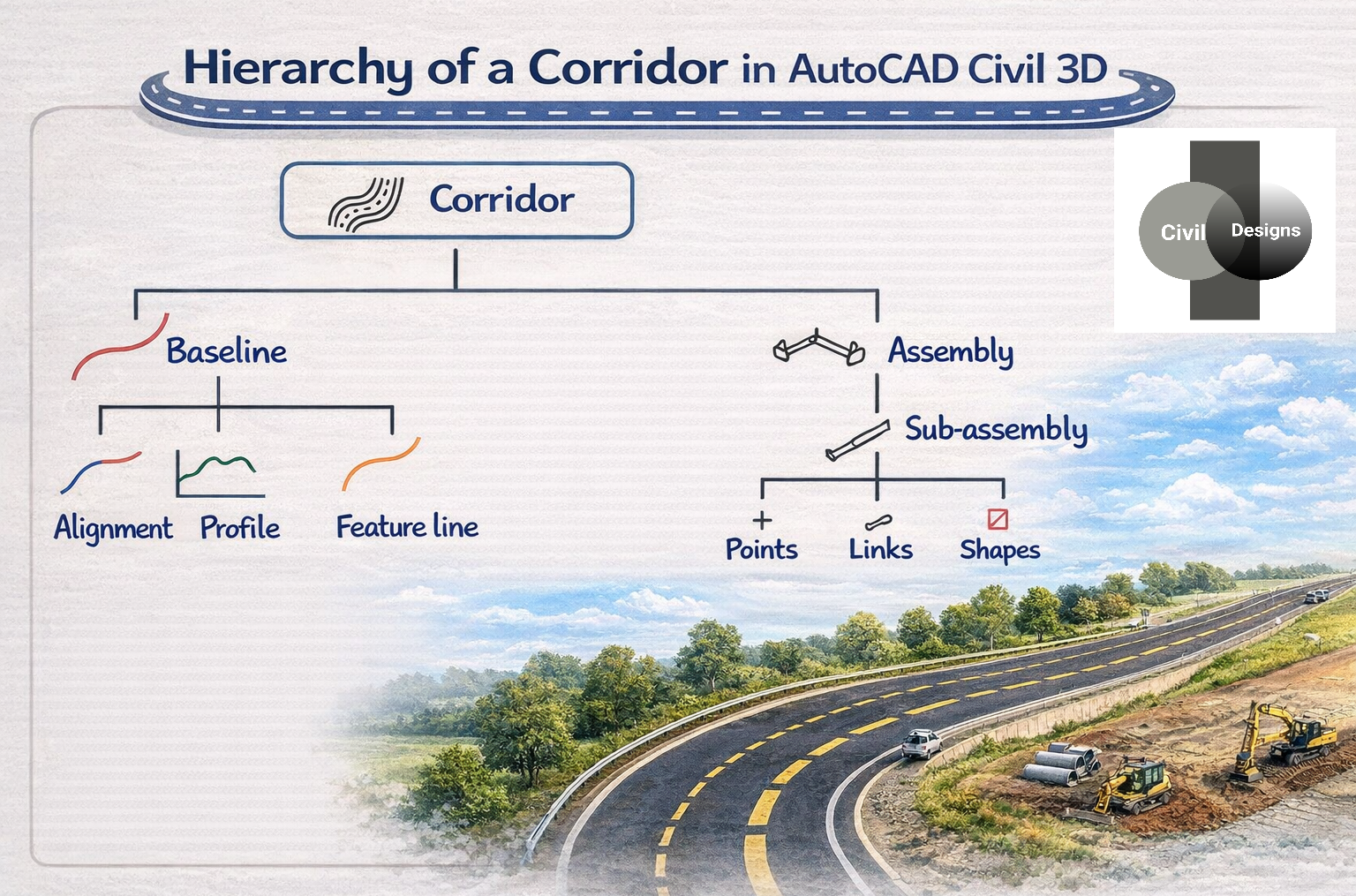
Understanding the Hierarchy of a Corridor
Civil 3D corridors follow a structured hierarchy. Each level plays a critical role in building a smart and adaptable model.
1. Corridor (Top Level)
The corridor sits at the top of the hierarchy. It acts as the container that holds all design components together.
Why it matters:
- Generates 3D road models
- Creates finished ground surfaces
- Calculates earthwork volumes
- Produces cross sections
Without a corridor, transforming design into a buildable model becomes extremely difficult.
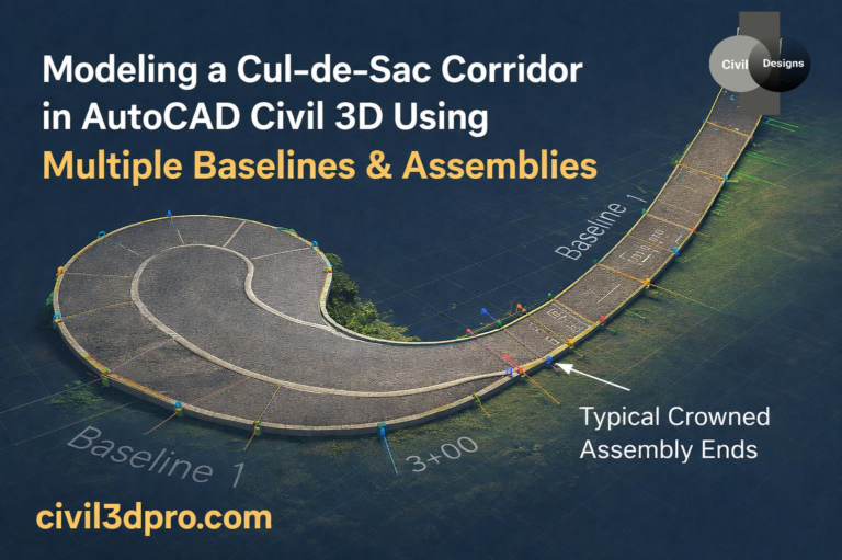
2. Baseline – The Foundation of the Corridor
A baseline is the controlling path of the corridor. It defines where the model will be applied.
A baseline typically consists of:
✅ Alignment – Defines the horizontal route
✅ Profile – Controls vertical elevations
✅ Feature Line – Can be used instead of alignment/profile in special designs such as grading areas
Pro Insight:
Most road projects use an alignment + profile as the baseline because it provides maximum control over geometry.
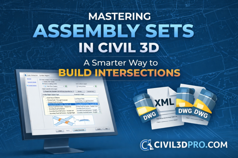
3. Assembly – The Road Template
An assembly represents the cross-sectional structure of the corridor. You can think of it as a template showing what the road should look like from side to side.
Typical elements include:
- Lanes
- Shoulders
- Curbs
- Sidewalks
- Slopes
- Drainage components
Once attached to a baseline, the assembly is repeated along the entire route to build the corridor automatically.
Why assemblies are powerful:
Change the assembly once, and the entire corridor updates instantly.
4. Subassembly – The Building Blocks
Assemblies are made from smaller components called subassemblies.
Each subassembly models a specific part of the infrastructure, such as:
- Traffic lanes
- Embankments
- Ditches
- Barriers
This modular approach gives engineers flexibility to design according to project standards.
5. Points, Links, and Shapes – The Geometry Engine
At the lowest level of the hierarchy are three critical geometric elements:
Points
Points define key positions in the cross-section — for example, the edge of pavement or shoulder break.
Links
Links connect points to form linear elements like slopes or pavement layers.
Shapes
Shapes are closed areas created by links. These are extremely important because they help calculate material quantities such as asphalt, base, and subbase.
Engineering Advantage:
Accurate shapes lead to reliable quantity takeoffs and better cost estimation.
Why Understanding Corridor Hierarchy is Important
Many beginners jump straight into corridor creation without understanding its structure — this often leads to design errors and rework.
When you clearly understand the hierarchy, you can:
✔ Design faster
✔ Reduce modeling mistakes
✔ Improve quantity accuracy
✔ Handle design changes easily
✔ Create more professional project deliverables
Simply put, it transforms you from a Civil 3D user into a smart infrastructure designer.
Real-World Example
Imagine designing a highway:
- The alignment defines the road path.
- The profile sets elevations and slopes.
- The assembly defines lane widths and shoulders.
- The corridor combines everything into a realistic 3D roadway.
If the road centerline shifts, the entire corridor updates automatically — including surfaces and earthwork volumes.
This is the true power of Civil 3D automation.
Expert Tip for Civil Engineers
👉 Always finalize your alignment and profile before building a corridor.
Major changes after corridor creation can slow down workflows and require rebuilds.
Also, use properly configured assemblies to match local design standards.
Conclusion
The hierarchy of a corridor is the backbone of intelligent infrastructure modeling in AutoCAD Civil 3D. From baselines to shapes, every component plays a role in creating accurate, dynamic, and construction-ready designs.
Once you master corridor structure, you unlock the full potential of Civil 3D — enabling faster workflows, smarter revisions, and highly precise engineering outputs.
Want to Master Corridors Faster?
Reading is great — but seeing the workflow in action is even better.
🎥 Head over to our YouTube Corridor Playlist to watch practical, real-world tutorials that will help you become confident in corridor design.
👉 Start Watching Now and level up your Civil 3D skills.
Don’t Forget to Join Our Facebook Page!
We regularly share:
✅ Civil 3D tutorials
✅ Engineering tips
✅ Industry insights
✅ Free learning material
👉 Follow our Facebook community and grow with thousands of engineers.