Understanding Corridors
A corridor consists of numerous dynamically linked Civil 3D objects, forming a cohesive design. To understand corridors, it is essential to study how these components integrate to create a 3D representation of your project.
Understanding the 3D Chain
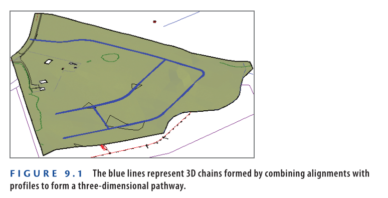
In Chapter 5, “Designing in 2D Using Alignments,” you created the 2D path of a road using alignments. In Chapter 7, “Designing Vertically Using Profiles,” you designed its vertical path using profiles. When combined, alignments and profiles create a 3D chain, which serves as the backbone of your design.
3D chains are visible in the drawing when viewed from a 3D perspective, as shown in Figure 9.1.
Understanding the 3D Chain
Since the 3D chain is dynamically linked to both the alignment and profile, any modification to either will automatically update the 3D chain and subsequently adjust the corridor.
Understanding the Assembly
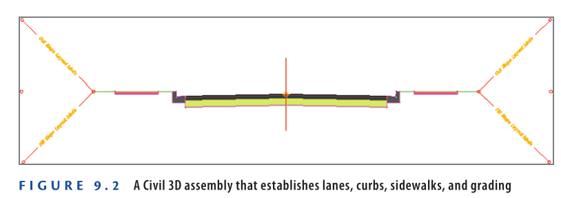
An assembly represents the cross-sectional geometry of the feature being designed. It defines the overall shape of the cross-section and differentiates its various components. For instance, a typical road cross-section may include asphalt pavement, base material, curbs, and sidewalks, as shown in Figure 9.2.
The components of an assembly are called subassemblies. These elements are dynamically linked, meaning changes in one can influence others. For instance, if a curb subassembly is placed at the edge of a lane subassembly, increasing the lane width will automatically shift the curb outward.
Understanding Assembly Insertions
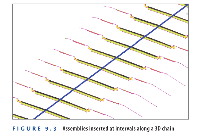
To generate a corridor, Civil 3D places instances of an assembly along the 3D chain at consistent intervals. These assembly insertions act as the structural framework of the 3D model, shaping the road one assembly at a time, as shown in Figure 9.3.
Since assembly insertions are dynamically linked to the 3D chain, any modification to the alignment or profile will automatically update the corridor. Additionally, these insertions are linked to the assembly, meaning any changes to the assembly will also reflect in the corridor.
Understanding Corridor Feature Lines
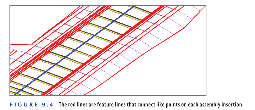
To create a structured framework along the length of the corridor, Civil 3D generates feature lines that connect assemblies (see Figure 9.4). These feature lines use a coding system to identify specific points they should pass through as they traverse each assembly.
Feature lines are linked to assembly insertions, which are linked to the 3D chain, creating an interconnected system. Rather than detailing each relationship, it is important to understand that everything within a corridor is dynamically related.
Understanding the Corridor Surface
If the assembly insertions along the 3D chain represent the structural framework of a corridor, the corridor surface acts like the outer shell—similar to the hull of a ship or the fuselage of an airplane. This surface forms the visible and functional top layer of the corridor (see Figure 9.5).
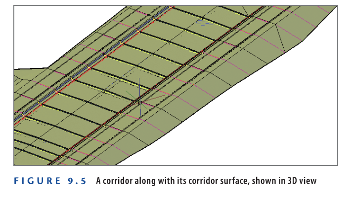
Although corridor surfaces appear in Prospector like other surfaces, they are directly generated from the corridor and remain dynamically linked to it. These surfaces can be displayed as contours, used to create surface profiles, and perform all standard surface-related functions.
Creating an Assembly
An assembly consists of multiple subassemblies. To create an assembly:
- Begin with an assembly baseline, represented by a vertical line with a midpoint base-point marker.
- Add subassemblies such as lanes, curbs, and ditches.
Before building an assembly, having a sketch of the typical cross-section is recommended. Exact dimensions are helpful but not essential, as subassemblies can be modified even after corridor creation.
Exercise 9.1: Create an Assembly
Follow these steps to create an assembly for a residential road design:
- Open Creating an Assembly.dwg which you cand download from Video tutorial description below.
- On the Home tab, click Assembly ➢ Create Assembly.
- In the Create Assembly dialog box:
- Enter Subdivision Road as the name.
- Set Code Set Style to All Codes With Hatching.
- Click OK.
- Click near the center of the top-right viewport to place the assembly baseline.
- On the Home tab, click the Tool Palettes icon.
- In the Tool Palettes window, right-click the gray strip labeled Tool Palettes and select Civil Imperial (Metric) Subassemblies.
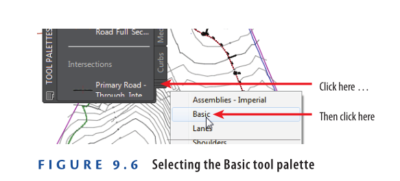
- Click the stack of tabs at the bottom of the Tool Palettes window, and
then click Basic, as shown in Figure 9.6.
- On the Basic tool palette, click BasicLane.
- In the Properties window:
- Ensure Side is set to Right.
- Click the midpoint marker of the assembly baseline.
- A lane subassembly is now attached to the assembly baseline.
- On the Basic tool palette, click BasicCurbAndGutter.
- In the Properties window, set Curb Height to 0.50 (0.15).
- Click the upper-right circle marker on the previously inserted lane subassembly.
- The curb and gutter subassembly is now attached.
- Press Esc to exit the insertion command.
- Select both the lane and curb subassemblies and click Mirror on the ribbon.
- Click the vertical red assembly baseline.
- Both sides now display lane and curb subassemblies.
- Save and close the drawing.
To review the completed exercise, open Creating an Assembly – Complete.dwg.
https://www.mediafire.com/file/t9t7841o4x9v11i/Creating+an+Assembly+-+Complete.dwg/file
Watch Complete Video Tutorial here for This Exercise:
What Are Subassemblies Made Of?
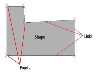
Subassemblies consist of three key components:
- Points – Defined locations in the subassembly.
- Links – Lines connecting two points.
- Shapes – Closed areas formed by three or more links.
Each point, link, and shape is assigned at least one code. These codes determine styles, behavior, and relationships within the design. A code set style is a collection of styles applied to multiple codes, ensuring consistency across the model.
Creating a Corridor
Considering the complexity and sophistication of a corridor, the process of creating one is quite simple. Once the alignment, profile, and assembly are set, they need to be linked together. While this is just the initial step, as you’ll see in the next exercise, creating a basic corridor involves only a few steps.
Exercise 9.2: Create a Corridor
In this exercise, you’ll create the initial corridor for Jordan Court.
- Open the drawing named Creating a Corridor.dwg which you can download from Videot Tutorial description below.
- On the Home tab of the ribbon, click Corridor.
- In the Create Corridor dialog box, do the following:
- For Name, enter Jordan Court.
- For Alignment, verify that Jordan Court is selected.
- For Profile, select Jordan Court FGCL.
- For Assembly, select Subdivision Road.
- Uncheck Set Baseline And Region Parameters.
- Click OK.
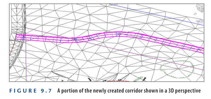
- Zoom in to the bottom-right viewport and notice the corridor that has been created there (see Figure 9.7).
- Save and close the drawing.
You can view the results of successfully completing this exercise by opening
Creating a Corridor – Complete.dwg.
https://www.mediafire.com/file/w1cjhs85upnu4bm/Creating+a+Corridor+Surface.dwg/file
Watch Complete Video tutorial here for this Exercise:
Applying Corridor Targets
One of the key strengths of corridors is their ability to interact with other objects in the drawing. Corridors can dynamically adjust their shape and size to fit existing features or newly designed components. This adaptability is achieved using special subassemblies that can be stretched, twisted, and modified as the design progresses. These subassemblies rely on corridor targets to function.
There are three types of targets that can be applied to a corridor:
- Surface Targets
- Width or Offset Targets
- Slope or Elevation Targets
Understanding Surface Targets
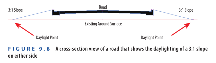
Surface targets are used when a corridor needs to interact with an existing surface. A common application is daylighting, where a slope extends from the design elevation to meet the existing ground surface. For instance, if a road section is elevated above the existing ground, daylighting helps create an embankment from the road’s elevation down to the original surface (see Figure 9.8).
Although daylighting is the most common use of surface targeting, it is also used for other design elements, such as:
- Establishing the cross slope of an existing road
- Setting the top elevation of a retaining wall
- Determining the depth of a pipe
- Various other surface interactions
Understanding Width or Offset Targets
Another type of corridor target is the width or offset target. This target is used to adjust the width of an object or control the distance between a point and the centerline (offset).
For example, an alignment can be set as a target to control the outside edge of a lane.
- If the alignment moves away from the centerline, the lane widens.
- If the alignment moves toward the centerline, the lane narrows (see Figure 9.9).
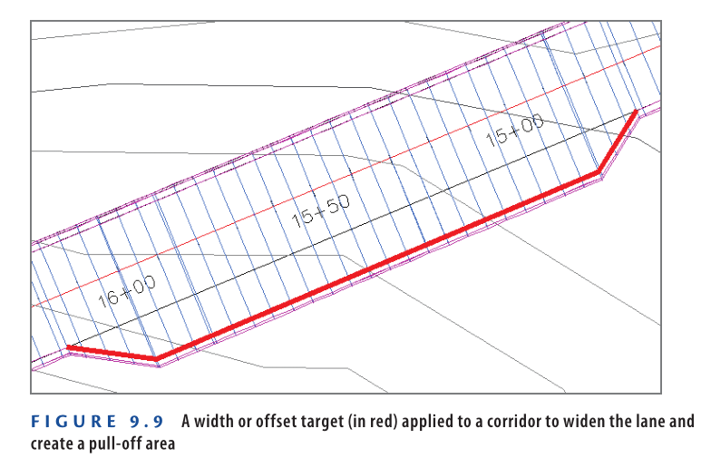
In addition to alignments, feature lines, survey figures, and polylines can also be used as width or offset targets. While lane widening is the most common use, other applications include:
- Controlling the location of a ditch
- Adjusting the width of a shoulder
- Managing the distance between a shoulder and a guardrail
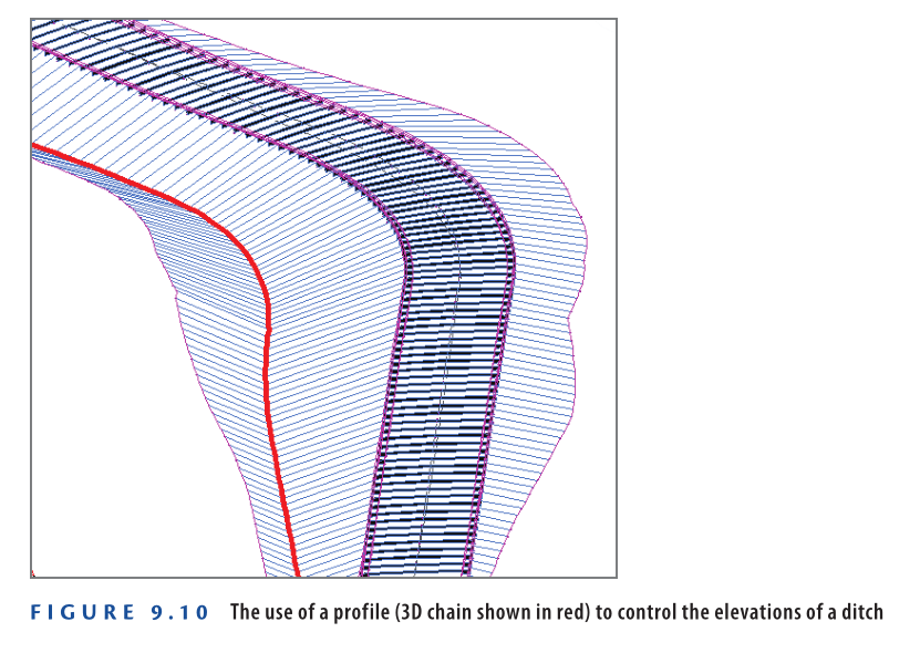
Understanding Slope or Elevation Targets
Slope or elevation targets are used to control the height of one or more components in a corridor. For example, they can ensure that a roadside ditch drains to a specific point, regardless of the adjacent road’s slope (see Figure 9.10).
The following objects can be used as slope or elevation targets:
- Profiles
- Feature lines
- Survey figures
- 3D polylines
Tying Proposed Elevations to Existing Elevations
The concept of daylighting is fundamental in land development. Since land development involves modifying terrain, some areas will have elevations that are either above or below the existing surface. Roads, parking lots, and other structures must transition smoothly between these elevations.
The most economical way to create this transition is by using soil, but steep slopes can lead to instability. Therefore, gradual slopes like 3:1 (three units horizontal to one vertical) are commonly used. One of the key aspects of land development design is ensuring a smooth tie-in between proposed elevations and existing elevations.
Enabling Target Behavior
Before using targets in a corridor, you must apply subassemblies that support targeting. Civil 3D provides hundreds of subassemblies, but not all have targeting capabilities.
For example:
- The BasicLane subassembly cannot use targets.
- If you need to vary the lane width, add a turning lane, or incorporate other features, you must select a target-compatible subassembly.
Exercise 9.3: Apply Subassemblies That Can Use Targets
In this exercise, you’ll add subassemblies to allow the corridor lane width to vary and enable the corridor to tie to the existing surface.
- Open the drawing named Adding Target Subassemblies.dwg which you can download from Video tutorial Description below.
- Open the Tool Palettes window and click the Basic tool palette.
- Click BasicLaneTransition. On the command line, type R and press Enter to enable the Replace option.
- In the upper-right viewport, click the right-lane subassembly. When prompted to select an attachment point for the highlighted subassembly, click the upper-left point of the curb and gutter, as shown in Figure 9.11.
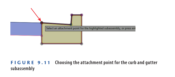
- Repeat steps 3 and 4 for the left-lane subassembly. This time, pick the upper-right corner point of the left curb and gutter subassembly.
- Press Esc to clear the current selection. Click the assembly baseline (the vertical line to which the subassemblies are attached), and then click Assembly Properties on the ribbon.
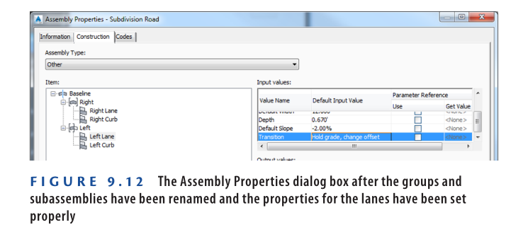
- In the Assembly Properties dialog box, follow these steps:a. Click the Construction tab. Click Group (1) twice to rename it, type Right, and press Enter. Do the same for Group (2) and rename it Left.
b. Under the Right group, rename the two subassemblies Right Lane and Right Curb. Do the same for the Left group, naming them Left Lane and Left Curb.
c. Click Right Lane. Then, under Input Values, scroll down to find the Transition value. Change it to Hold Grade, Change Offset.
d. Repeat step c for Left Lane.
Once completed, your Assembly Properties dialog should look similar to Figure 9.12.
- Click OK to close the Assembly Properties dialog box and return to the drawing.
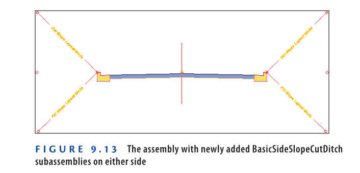
- Open the Basic tool palette and select BasicSideSlopeCutDitch.
- Click the marker in the upper-left corner of the Left Curb subassembly. Then, click the marker in the upper-right corner of the Right Curb subassembly.
After completing these steps, your assembly should resemble Figure 9.13.
- Press Esc to end the current command. Click the right BasicSideSlopeCutDitch subassembly, then click Subassembly Properties on the ribbon.
- In the Subassembly Properties dialog box, go to the Information tab and rename it Right Daylight.
- Repeat steps 11 and 12 for the left subassembly, naming it Left Daylight.
- Save and close the drawing.
To review your results, open Adding Target Subassemblies – Complete.dwg.
https://www.mediafire.com/file/g7ev7k5jbm8n703/Adding+Target+Subassemblies+-+Complete.dwg/file
Watch Complete Video tutorial here for this Exercise:
Assigning Targets
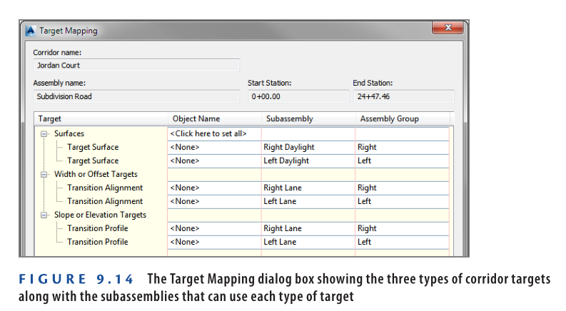
The Target Mapping dialog box allows you to assign targets within a corridor. It categorizes targets into:
- Surface Targets
- Width or Offset Targets
- Slope or Elevation Targets
Only subassemblies capable of using these targets will appear in the dialog box (Figure 9.14). However, not all available targets need to be assigned—many remain set to <None> by default.
To assign a target in the Target Mapping dialog box:
- Click the cell in the Object Name column corresponding to the subassembly you want to assign a target to.
- A dialog box will appear, allowing you to select objects in the drawing either graphically or by name.
- Choose the appropriate object and confirm the selection.
This process helps define how the corridor interacts with surfaces, offsets, or elevation constraints.
Corridor Region
In step 3, you are prompted to select a region to edit. A region is a section of your corridor that starts at one station and ends at another. Initially, all corridors have a single region spanning their full length. However, as the design progresses, corridors are typically divided into multiple regions.
Exercise 9.4: Assign Targets
In this exercise, you will assign targets to the corridor to enable daylighting and create a turn lane for Jordan Court.
- Open the drawing Applying Corridor Targets.dwg which you can download from Video tutorial below.
- Select the corridor in the drawing and click Edit Targets on the ribbon.
- When prompted to select a region, click anywhere within the corridor in the left viewport.
- In the Target Mapping dialog box, under Width or Offset Targets, click <None> in the Object Name column next to the Left Lane subassembly.
- In the Set Width or Offset Target dialog box, under Select Object Type to Target, choose Feature Lines, Survey Figures, and Polylines.
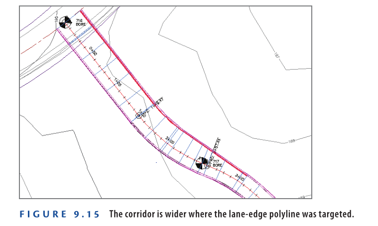
- Click Select From Drawing, then zoom into the beginning of Jordan Court where it meets Emerson Road in the left viewport.
- Click the red polyline representing the intended path of the left lane’s edge and press Enter.
- Click OK twice to return to the drawing. The corridor expands near the entrance, as shown in Figure 9.15. This widening provides additional space for a turning lane.
- Click within the corridor to reopen the Target Mapping dialog box.
- In the Target Mapping dialog box, click the cell next to Surfaces that reads <Click Here To Set All>.
- Select EG and click OK, then click OK again to close the Target Mapping dialog box.
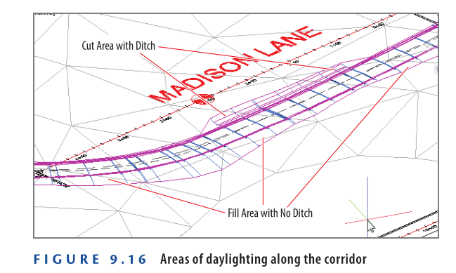
Pan around in the lower-right viewport to view the 3D representation of the corridor. You should now see additional geometry along the corridor edges (see Figure 9.16). This represents the daylighting that has been applied. The daylighting geometry appears wider in some areas due to the presence of low ground where a ditch has been automatically created. This ditch formation is controlled by the BasicSideSlopeCutDitch subassembly.
- Save and close the drawing.
You can review the completed exercise results by opening Applying Corridor Targets – Complete.dwg.
https://www.mediafire.com/file/lj3wdmd22famfuq/Applying+Corridor+Targets+-+Complete.dwg/file
Watch Complete Video Tutorial here for this Exercise:
Creating Corridor Surfaces
In Chapter 4, you learned about using surfaces to model existing terrain. Surfaces provide capabilities such as displaying contours, labeling elevations, and creating surface profiles. Similarly, you can create a surface for a corridor, allowing for advanced analysis and visualization.
Cut and Fill
The terms cut and fill are widely used in land development:
- Cut occurs when the road is below the existing ground, requiring an upward slope to daylight. This means earth must be removed to construct the road.
- Fill occurs when an area needs additional material to achieve the required elevation.
Cut and fill also refer to earthwork volumes, representing how much material needs to be removed (cut) or added (fill) for construction.
Corridor Surfaces
Corridor surfaces are integrated into the corridor model but appear in Prospector like any other Civil 3D surface. You use the Corridor Surface dialog box to create a surface and define the data that should be included.
Key steps:
- Use links and feature lines based on assigned codes.
- Add boundaries using the Boundaries tab.
- Use corridor extents, coded feature lines, or manual polylines for boundaries.
Exercise 9.5: Create a Corridor Surface
In this exercise, you will create a finished ground (FG) surface for the Jordan Court corridor.
- Open Creating a Corridor Surface.dwg which you can download from Video Tutorial Description below.
- Select the Jordan Court corridor, then click Corridor Surfaces on the ribbon.
- In the Corridor Surfaces dialog box, click the leftmost icon to create a new corridor surface.
- Rename the surface to Jordan Court FG.
- Ensure that Data Type is set to Links and Code is set to Top, then click the plus sign to add the Top coded links.
- Click OK. If the Corridor Properties – Rebuild dialog box appears, click Rebuild The Corridor.
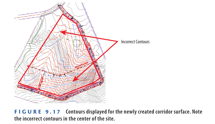
Now, you should see contours in the left viewport and TIN lines in the bottom-right viewport. However, there may be incorrect surface data in the center of the site (see Figure 9.17).
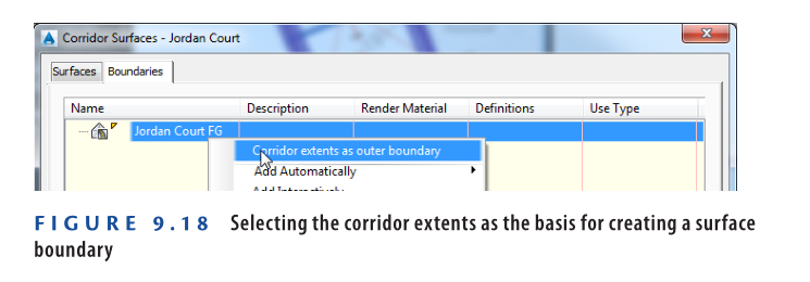
7: If the corridor is no longer selected, click the corridor in the drawing, then click Corridor Surfaces again. Navigate to the Boundaries tab in the Corridor Surfaces dialog box.
8: Right-click Jordan Court FG, then select Corridor Extents As Outer Boundary, as shown in Figure 9.18.
- Click OK to return to the drawing. If the Corridor Properties – Rebuild dialog box appears, click Rebuild The Corridor.
Now, the surface is contained within the corridor extents, ensuring that contours appear only where valid surface data exists.
- Save and close the drawing.
You can review the completed exercise by opening Creating a Corridor Surface – Complete.dwg.
https://www.mediafire.com/file/1mu67x3l10thpfg/Creating+a+Corridor+Surface+-+Complete.dwg/file
Watch Complete Video here for this Exercise:
Alternate Corridor Surfaces
In this example, you created a surface representing the finished ground (FG) elevations of the corridor. However, corridors contain multiple codes, such as pave, datum, curb, and more. While some codes may not be useful for surface creation, others are highly valuable.
For example, the datum code represents the underside of road materials, defining the roadbed that must be excavated before placing stone, concrete, or asphalt. Since earthmoving is a crucial aspect of road construction, using the datum surface helps in estimating excavation volumes accurately.
Intersections in Civil 3D
One of the most advanced applications of targets and regions is designing an intersection. This process requires multiple baselines, regions, and targets to connect two roads and ensure a smooth transition between them.
To simplify intersection design, Civil 3D provides the Create Intersection command, which automates the creation and management of intersection components.
Intersection Wizard
When launching the Create Intersection command, the Intersection Wizard guides you through several dialog boxes to define the intersection parameters:
- General: This section includes details such as the intersection name, description, and styles.
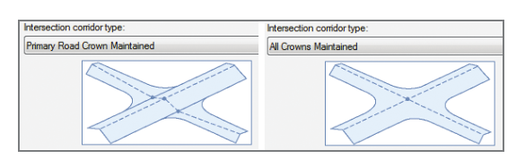
- Intersection Type: You must choose between two design options:
- Primary Road Crown Maintained – Keeps the crown of the primary road while adjusting the secondary road.
- All Crowns Maintained – Preserves the crowns of both roads, creating a more complex intersection design.
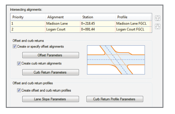
Geometry Details in Intersection Design
In the Geometry Details dialog, you specify key parameters that control the horizontal and vertical geometry of the intersection.
Key Settings in Geometry Details Dialog
- Profile Selection:
- Choose a profile for each alignment, which determines the centerline elevations of the intersecting roads.
- Horizontal Geometry Settings:
- Curb Return Parameters: Adjust the radius of the curb return to ensure smooth vehicle movement.
- Offset Parameters: Define the offset distances to maintain proper lane widths and turning clearances.
- Vertical Geometry Settings:
- Lane Slope Parameters: Set the cross slope of lanes to maintain proper drainage.
- Curb Return Profile Parameters: Control the vertical alignment of curb returns for smooth elevation transitions.
These settings ensure that the intersection geometry aligns seamlessly with the surrounding road network, optimizing both safety and functionality.
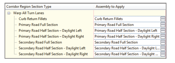
Corridor Regions in Intersection Design
The Corridor Regions dialog allows you to assign different assemblies to specific parts of the intersection design. This set of assemblies and their assignments is known as an assembly set.
Key Aspects of Corridor Regions
- Assigning Assemblies:
- Different parts of the intersection (main road, side road, curb returns, etc.) require unique assemblies.
- These assemblies define lane widths, slopes, curb structures, and other design elements.
- Use of Assembly Sets:
- Assembly sets are predefined by a CAD manager or lead designer.
- For new designers, these sets are typically provided to ensure consistency across projects.
By properly assigning assemblies in the Corridor Regions dialog, you ensure a smooth transition between road sections, maintaining design accuracy and construction feasibility.
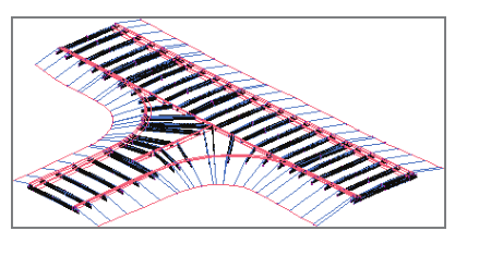
After completing the Create Intersection command, your drawing will generate a fully detailed 3D representation of the intersection.
Key Features of the Completed Intersection
- New Baselines, Regions, and Targets:
- The intersection design automatically includes additional baselines, corridor regions, and targets to ensure smooth connectivity.
- Dynamic Design Updates:
- Any modifications to the intersection or surrounding corridor elements will be automatically reflected while maintaining proper geometric relationships.
- Seamless Corridor Integration:
- The intersection remains in sync with adjacent portions of the corridor, preventing design inconsistencies.
This automated approach in Civil 3D 2025 streamlines intersection modeling, ensuring accurate and efficient design updates throughout the project lifecycle.
Now You Know
Now that you have completed this chapter, you understand the structure of a corridor and how alignments, profiles, and assemblies work together to create a 3D corridor model. You can develop an assembly representing a standard road cross-section and then generate a corridor using that assembly, along with an alignment and a profile in the drawing. You can apply target-capable subassemblies and set up the corridor to utilize available targets for daylighting and lane width variations. Finally, you can create corridor surfaces to extract critical surface data for use in other aspects of the design.
You are now prepared to start creating and managing corridors in a real-world production setting.