Creating Surface Profiles
One of the initial steps in designing the vertical alignment of a linear feature is to analyze the terrain’s shape along that feature. Surfaces are used to generate 3D models of the ground, and they serve multiple purposes beyond contour display or spot elevation labeling. One key use is generating profiles from surface data, aiding in the design of roads, channels, pipelines, and similar projects.
A surface profile is created using surface data and maintains a dynamic link to the referenced surface and alignment. If either changes, the surface profile updates automatically.
Exercise 7.1: Create a Surface Profile
- Open the Surface Profile.dwg file which you can download from the description of Video tutorial below.
- Select the Jordan Court alignment in the drawing and click Surface Profile from the contextual ribbon.
- In the Create Profile From Surface dialog box, ensure Jordan Court is selected as the alignment.
- Under Select Surfaces, choose EG, then click Add and OK.
- In Prospector, expand Alignments ➢ Centerline Alignments ➢ Jordan Court ➢ Profiles. You will find EG – Surface (1) listed under Profiles. The small orange triangle next to Jordan Court indicates dependent objects, including the newly created profile.
- Right-click EG – Surface (1) and select Properties.
- On the Information tab of the Profile Properties dialog box, rename it to Jordan Court EGCL and click OK.
Although Prospector confirms the profile’s creation, it isn’t visible graphically. To display it, a profile view is required, which leads to the next section.
- Save and close the drawing.
You can view the results of successfully completing this exercise by opening - Surface Profile – Complete.dwg
https://www.mediafire.com/file/89rwbwvqxax0xoj/Surface+Profile+-+Complete.dwg/file
Watch Complete video Tutorial for this Exercise:
Displaying Profiles in Profile Views
In AutoCAD Civil 3D 2025, a profile must be displayed using a profile view. A profile view is a grid that represents stations on the x-axis and elevations on the y-axis. The stations along the alignment and their corresponding elevations are plotted, forming a line that depicts terrain changes. Profile views also include labels like axis labels and titles for better readability. Additional details, such as bands, will be covered in Chapter 8: Displaying and Annotating Profiles.
Exercise 7.2: Create a Profile View
- Open Profile View.dwg which you can download from the Video description below.
- Select the Jordan Court alignment and click Profile View from the contextual ribbon.
- In the Create Profile View – General dialog box, click Create Profile View.
- When prompted for the profile view origin, click a point in the open area to the east of the project.
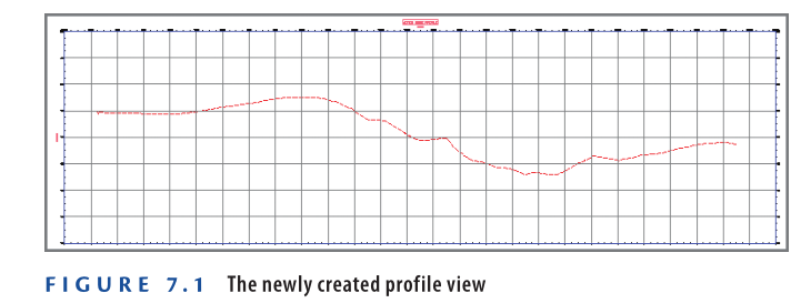
A new profile view will be inserted into the drawing, displaying the surface profile.
5: Save and close the drawing.
You can check the results of this exercise by opening Profile View – Complete.dwg.
https://www.mediafire.com/file/tq94pbq93rvcu6z/Profile+View+-+Complete.dwg/file
Watch Complete Video tutorial here for this exercise:
Now, you can analyze the terrain along the Jordan Court alignment. The profile reveals a flat area at the beginning, followed by a steep drop into a low area, and a gradual rise toward the end. The jagged appearance of the line suggests moderately rough terrain. This graphical depiction helps visualize necessary adjustments to ensure a smooth and safe driving experience.
Creating Design Profiles
The surface profile shows that the existing path of Jordan Court is unsuitable for driving. To correct this, a design profile (or layout profile) must be created.
In Civil 3D 2025, design profiles consist of tangents (straight-line segments) and connecting curves. These profiles are similar to alignments but viewed from the side. The process of creating a profile follows a method similar to alignment layout using the Profile Layout Tools toolbar.
Profile Terminology
Understanding the following terms will help when working with design profiles:
- Tangent – The straight-line sections of a profile.
- PVI (Point of Vertical Intersection) – The point where two tangents intersect.
- PVC (Point of Vertical Curvature) – The start of a vertical curve.
- PVT (Point of Vertical Tangency) – The end of a vertical curve.
- Parabolic Curve – A vertical curve that follows a parabolic shape instead of having a constant radius.
- Circular Curve – A vertical curve with a constant radius.
- Asymmetric Curve – A vertical curve made up of two back-to-back parabolic curves.
- Crest Curve – A curve at the top of a hill, where the incoming grade is steeper than the outgoing grade. The PVI is above the curve.
- Sag Curve – A curve at the bottom of a valley, where the incoming grade is shallower than the outgoing grade. The PVI is below the curve.
Exercise 7.3: Design a Profile
- Open Design Profile.dwg which you can download from Video Tutorial Description below.
- Click one of the grid lines in the Jordan Court profile view, then select Profile Creation Tools from the contextual ribbon.
- In the Create Profile – Draw New dialog box, enter Jordan Court FGCL as the Name.
4: Ensure Profile Style is set to Design Profile and Profile Label Set is set to _No Labels, then click OK.
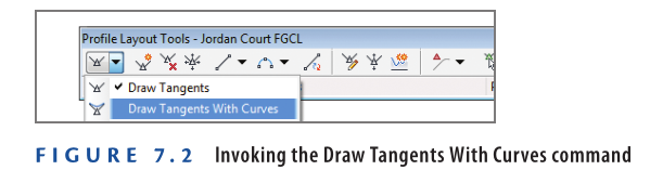
5: On the Profile Layout Tools toolbar, click the small black triangle on the far-left button to expand the options, then select Draw Tangents With Curves see Figure 7.2.
- Press and hold Shift, then right-click and select Osnap Settings from the context menu.
- In the Drafting Settings dialog box, uncheck all options except Object Snap On (F3) and Center, then click OK.
- Click the center of the circle marked A, then click the remaining circles in order from left to right. After selecting the circle marked G, press Enter.
- The newly created profile will have a PVI at each selected point.
- Since you used Draw Tangents With Curves, all PVIs (except the first and last) will include vertical curves.
- Save and close the drawing.
You can check the results of this exercise by opening Design Profile – Complete.dwg.
https://www.mediafire.com/file/baxr1gy8q7tjiib/Design+Profile+-+Complete.dwg/file
Watch Complete Video Tutorial here for this Exercise:
Editing Profiles
As discussed in Chapter 5, “Designing in 2D Using Alignments,” it is common practice to create a rough design first and then refine it for the final version. This approach is especially useful for profiles, where the initial design aims to match the existing ground as closely as possible while minimizing unnecessary changes.
Matching the existing ground reduces construction costs since less earth needs to be excavated. Earthmoving costs are based on the volume of material moved, so minimizing excavation helps control expenses.
Once the initial profile is created, it must be refined based on factors such as road performance, avoiding underground and overhead obstacles, and ensuring proper drainage. These refinements often involve input from multiple project stakeholders.
Civil 3D 2025 offers powerful tools for editing profiles both graphically and numerically, making the refinement process efficient and precise.
Exercise 7.4: Edit a Profile with Grips
Profiles, like alignments, include specialized grips for efficient editing. In this exercise, you will use grips to modify the Jordan Court design profile.
- Open the Graphical Editing.dwg which you can download from Video Tutorial description.
- Click on the blue Jordan Court FGCL profile to reveal its grips.
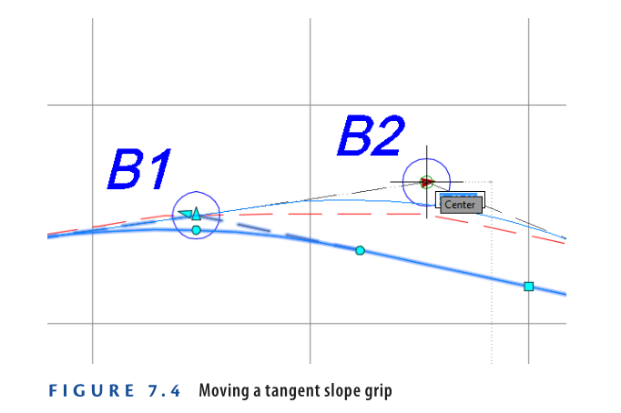
3: At the circle marked B1, click the triangle grip on the right and drag
it to the center of the circle marked B2, as shown in Figure 7.4.
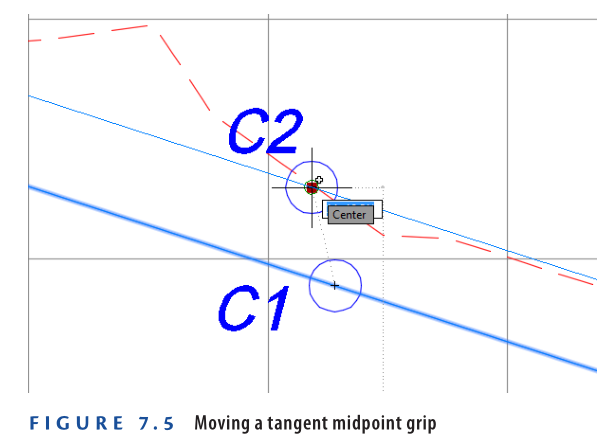
4: Click the square grip at the center of circle C1, and move it to the
center of circle C2, as shown in Figure 7.5.
.
5: Click the circular grip located at the center of circle D1, and move it
to the center of circle D2, as shown in Figure 7.6.
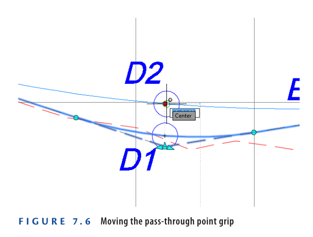
This is an example of moving the pass-through grip, forcing the curve
to pass through a given point while adjusting the length of the curve.
- Click the circular grip at the center of circle E1, and move it to the
center of circle E2, as shown in Figure 7.7.
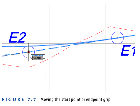
This is an example of moving the endpoint grip of the curve, which also moves the start point to adjust the length of the curve.
- Save and close the drawing.
You can view the results of successfully completing this exercise by opening Graphical Editing – Complete.dwg.
https://www.mediafire.com/file/vukrodux4bkxqsu/Graphical+Editing+-+Complete.dwg/file
Watch Complete Video Tutorial here for this Exercise:
Profile Locking
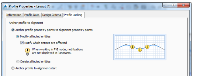
When an alignment is edited, profiles respond differently depending on their type. Surface profiles automatically update to match the revised alignment path. However, design profiles behave differently due to a feature called profile locking.
Profile locking is available in the Profile Properties dialog under a dedicated tab. This feature allows you to link profile geometry with alignment geometry, ensuring that Civil 3D 2025 maintains key design features in sync with alignment changes.
Exercise 7.5: Edit a Profile Using the Profile Layout Tools
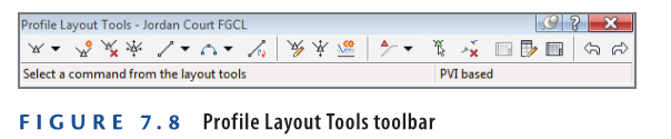
Grips are useful for modifying existing geometry, but when you need to add a PVI (Point of Vertical Intersection) or draw a curve, the Profile Layout Tools toolbar is required (see Figure 7.8). This toolbar is the same one used to create a profile initially and provides advanced editing options for refining profile geometry.
In this exercise, you’ll use the Profile Layout Tools to refine the Jordan Court profile, aligning it better with the existing ground and simplifying the design.
- Open the Editing Tools.dwg which you can download from the Video Tutorial Description below.
- Click the Jordan Court FGCL profile, then select Geometry Editor from the ribbon.
- This opens the Profile Layout Tools toolbar.
- On the Profile Layout Tools toolbar, click Insert PVI. While holding the Shift key, right-click and select Endpoint.
- Zoom in to the left end of the profile, and click the sharp break in the existing ground profile at the center of the circle marked A.
- On the Profile Layout Tools toolbar, click Delete PVI, then click inside the circle marked B.
- This removes the PVI at this location, eliminating the slight bend in the profile.
- On the Profile Layout Tools toolbar, click Insert PVIs – Tabular.
- In the Insert PVIs dialog box, enter:
- Station: 19+10 (0+582)
- Elevation: 174.00 (53.000)
- Press Enter to create a new line, then enter:
- Station: 21+55 (0+655)
- Elevation: 173.5 (52.750)
- Click OK.
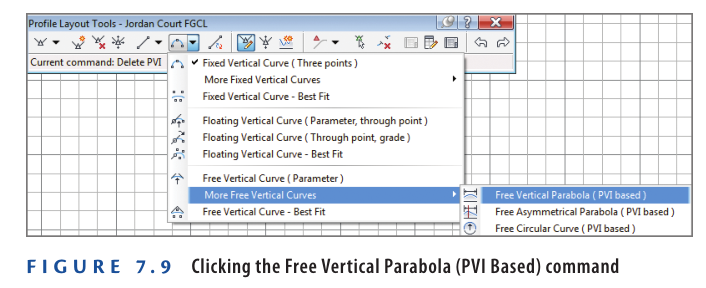
- On the Profile Layout Tools toolbar, click the black triangle next to the curves button to open the curves menu.
- Select More Free Vertical Curves → Free Vertical Parabola (PVI Based), as shown in Figure 7.9.
Completing Exercise 7.5
- Click inside the circle marked C, type 150 (45) for the curve length, and press Enter.
- Click inside the circle marked D, type 200 (60) for the curve length at the command line, and press Enter.
- Press Enter to end the command.
- Save and close the drawing.
To verify the results, open Editing Tools – Complete.dwg.
https://www.mediafire.com/file/o175lnw0c6jjmsh/Editing+Tools+-+Complete.dwg/file
Watch Complete Video Tutorial here for this Exercise:
Exercise 7.6: Edit a Profile Using Profile Grid View
When precise adjustments are needed, Profile Grid View in Panorama provides a tabular view of profile geometry, allowing direct edits to PVI stations and elevations.
- Open Profile Grid View.dwg which you can download from the video tutorial description below.
- Click the Jordan Court FGCL profile, then select Geometry Editor on the ribbon.
- Click Profile Grid View to open the Profile Entities tab, displaying the numerical version of the profile geometry.
- Modify Item 3:
- Station: 2+70.00 (0+080.00)
- PVI Elevation: 188.00 (57.00)
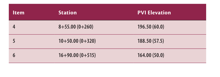
- Update the remaining items as follows:
- Close Panorama.
- The drawing may not look significantly different since the changes were subtle.
- Save and close the drawing.
To verify the results, open Profile Grid View – Complete.dwg.
https://www.mediafire.com/file/4qsdyh9a4k6rzlz/Profile+Grid+View+-+Complete.dwg/file
Watch Complete Video here for this Exercise:
Keep It Simple
The goal of Exercise 7.6 was to simplify the profile design. In most cases, precise decimal values (e.g., 0.01) are unnecessary. Rounding station and elevation values to whole numbers makes it easier for contractors and surveyors to interpret and stake out the design accurately, reducing errors.
However, PVIs for items 1, 2, and 9 were not rounded because they correspond to specific locations and elevations that must be met. Items 7 and 8 were already rounded when using the Insert PVIs – Tabular command in the previous exercise.
Exercise 7.7: Edit a Profile Using Component-Level Editing
The second method for numerically editing a profile design is known as component-level editing. This method allows you to modify individual profile components, such as lines or vertical curves, through a dedicated editing window. To do this, click the Sub-entity Editor button on the Profile Layout Tools toolbar and then use the Pick Sub-entity tool to select the profile section you wish to edit.
In this exercise, you will use component-level editing to modify the Jordan Court design profile.
- Open the drawing Profile Component Level Editing.dwg which you can download from Video Tutorial Description below.
- Select the Jordan Court profile and click Geometry Editor from the ribbon.
- On the Profile Layout Tools toolbar, click Profile Layout Parameters to open the dialog box (it will initially appear blank).
- Click Select PVI and then select the lowest point on the Jordan Court FGCL profile.
- Set Profile Curve Length to 275 (80). Close both the Profile Layout Parameters dialog box and the Profile Layout Tools toolbar.
- The modification is subtle, so the drawing may not visibly change significantly.
- Save and close the drawing.
To view the completed version of this exercise, open Profile Component Level Editing – Complete.dwg.
https://www.mediafire.com/file/p2qmj1lx9inbt4w/Profile+Component+Level+Editing+-+Complete.dwg/file
Watch Complete Video here for this Exercise:
Using Design Check Sets and Criteria Files
Design criteria files and check sets help validate designs in real-time by detecting errors or inconsistencies. These tools are customizable based on local regulations, company standards, or personal preferences. However, they should not replace fundamental design knowledge. They serve as a validation tool to ensure correct application of design principles rather than a substitute for expertise.
Exercise 7.8: Apply a Design Check Set
A design check set consists of multiple design checks for profiles, categorized into line and curve checks. When applied, Civil 3D 2025 flags violations with a yellow triangular shield containing an exclamation mark. Hovering over this symbol reveals details about the issue.
In this exercise, you will apply a design check set to the Jordan Court profile and resolve any detected design violations.
- Open Design Check Set.dwg which you can download from Video Tutorial description below.
- Select the Jordan Court FGCL profile and click Profile Properties on the ribbon.
- In the Profile Properties dialog box, navigate to the Design Criteria tab and enable Use Criteria-Based Design.
- Check Use Design Check Set and choose Subdivision.
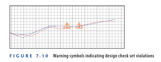
- Click OK to close the dialog box. Press Esc to deselect the profile and observe the two yellow warning shields near the right end of the profile Figure 7.10.
- Zoom into the area where the warning symbols are displayed and hover over the leftmost symbol.
- The tooltip indicates that the grade check is violated for this tangent.
- Click the profile to activate grips, then select the PVI grip to the left of the warning symbol and move it upward.
- Adjust the PVI downward incrementally until both tangent warning symbols disappear, ensuring compliance with the design check.
- Press Esc to clear the selection, then hover over the remaining warning symbol.
- Click the profile to activate grips, select a circular grip at either end of the curve, and extend the curve outward.
- When the curve length is sufficient, the warning symbol disappears.
- Save and close the drawing.
To verify the completed exercise, open Design Check Set – Complete.dwg.
https://www.mediafire.com/file/i9l9pmd1g49jnpc/Design+Check+Set+-+Complete.dwg/file
Watch Complete Video here for this Exercise:
Exercise 7.9: Apply a Design Criteria File
Design criteria files function similarly to design check sets by flagging violations but offer more advanced geometric analysis.
- Open Design Criteria File.dwg which you can download from Video Tutorial Description below.
- Select the Jordan Court FGCL profile and click Profile Properties from the ribbon.
- Navigate to the Design Criteria tab and check both Use Criteria-Based Design and Use Design Criteria File.
- Click the button next to the file path and select:
- Autodesk Civil 3D Imperial (2011) Roadway Design Standards.xml
- Or Autodesk Civil 3D Metric (2011) Roadway Design Standards.xml
- Click Open.
- Ensure Use Design Check Set is unchecked.
- Click OK and press Esc to clear the selection.
- Hover over the leftmost warning symbol.
- The tooltip indicates that the minimum passing sight distance requirement is not met see Figure 7.11.

8: Hover over the warning symbol at the lowest point of the profile.
9: Click the Jordan Court FGCL profile and select Geometry Editor from the contextual ribbon tab.
10: On the Profile Layout Tools toolbar, click Profile Grid View.
11: In the Panorama window, scroll to the right until you locate the Minimum K For Headlight Sight Distance column.
- A warning symbol appears in the row for Item 6, indicating that the required K value is 26.000 (9.000) Figure 7.12.
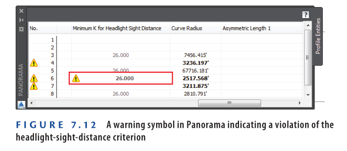
- In the Panorama window, scroll left to locate the K Value column. Change the K value for Item 6 to 26 (9).
- Update the Profile Curve Length for Item 6 to 225 (75).
- This adjustment generates a K value of 27.193 (9.010), ensuring the warning symbol disappears.
- Save and close the drawing.
To verify the completed exercise, open Design Criteria File – Complete.dwg.
https://www.mediafire.com/file/1vqby2u3u23a8e8/Design+Criteria+File+-+Complete.dwg/file
Watch Complete Video here for This Exercise:
What’s So Special about K?
The K value measures the abruptness of a vertical curve in road design. A low K value can create sharp transitions, making roads uncomfortable or even dangerous at higher speeds.
- Formula: K = Curve Length / Change in Grade
- Higher K Value: Longer, smoother curves → Safer & more comfortable
- Lower K Value: Short, abrupt curves → Uncomfortable & potentially hazardous
Headlight Sight Distance
Headlight sight distance ensures safe visibility at night. If curves obstruct a driver’s view of obstacles, the road becomes unsafe.
- Higher speeds require longer sight distances for reaction time.
- Proper K values help maintain sufficient visibility and prevent accidents.
Now You Know
After completing this chapter, you can effectively create, display, analyze, and modify profiles for both existing and proposed designs.
- Surface Profiles: Display existing terrain along an alignment.
- Design Profiles: Define proposed elevations for roads and other infrastructure.
- Editing Methods: Use graphical, command-driven, and numerical tools to modify profiles.
- Design Validation: Apply design check sets and criteria files to ensure compliance and make necessary adjustments.
With these skills, you’re ready to work with profiles in real-world projects within a production environment.