Displaying Pipe Networks using Styles
Pipe and structure styles are among the most advanced style options in AutoCAD® Civil 3D® 2025. These styles offer flexible display options for pipe network components in plan, profile, 3D model, and section views. This flexibility is essential when working with multiple system types in a single drawing, where clear graphical distinction is needed.
Applying Structure, Fitting, and Appurtenance Styles
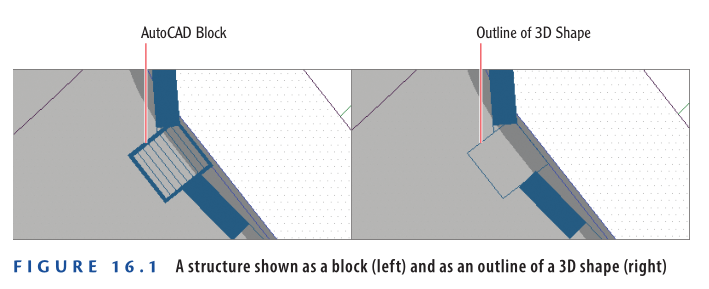
Civil 3D 2025 provides essential styling tools for structures, fittings, and appurtenances. In plan view, a structure can be shown either as a 3D shape outline or represented by an AutoCAD® block. When using a block, its size can be defined by the drawing scale, a fixed scale, or the actual part dimensions. For example Figure 16.1, a structure can appear as a block on the left and a 3D outline on the right, depending on the selected display method.
Profile View Display Options for Structures
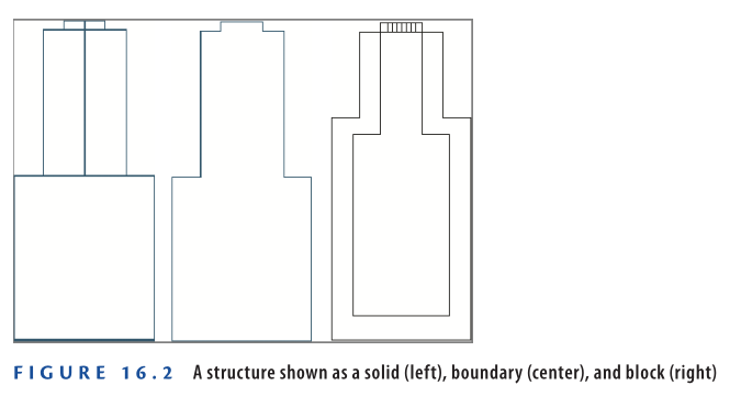
In AutoCAD® Civil 3D® 2025, structures can be displayed in profile view using three main methods:
Solid
This method shows a section cut of the 3D model, accurately representing the size, shape, and dimensions of the part. Interior details of the structure are visible with this option.
Boundary
This displays the structure as an outline of the 3D model. It accurately represents the exterior dimensions but omits interior details.
Block
A block (see Figure 16.2, right ) is inserted and scaled, typically with vertical scaling to match the part height and horizontal scaling to match the part width. While blocks can visually represent the part effectively, they may not precisely match the actual dimensions due to scaling.
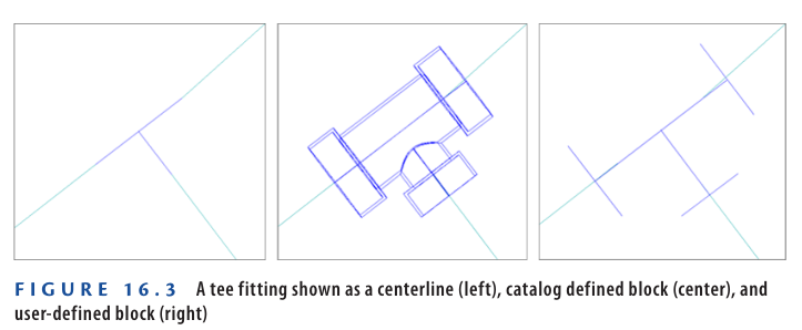
There are three ways to display fittings and appurtenances (Figure 16.3).
Plan View Display Options for Fittings and Appurtenances
In AutoCAD® Civil 3D® 2025, fittings and appurtenances can be displayed in plan view using the following options:
Centerline
As shown in Figure 16.3 (left), this is the simplest display method and represents the fitting or appurtenance as a single line.
Catalog Defined Block
Shown in Figure 16.3 (center), this option displays the actual 3D form of the fitting or appurtenance in plan view, as defined in the part catalog.
User Defined Block
As seen in Figure 16.3 (right), this allows the use of any AutoCAD block to represent the fitting or appurtenance in plan view.
In profile view, fittings are shown as outlines, while appurtenances appear as symbols representing their type. These options are fixed and cannot be customized like plan view displays.
Typically, CAD managers handle style configuration, but understanding these display methods is helpful when requesting custom styles.
Exercise 16.1: Control the Display of Structures
In this exercise, you will apply different styles to gravity and pressure structures to observe how their visual representation affects design decisions.
- Open the drawing named Applying Structure and Fitting Styles.dwg which you can download from video tutorial description.
- In the left viewport, click the sanitary manhole (marked with an “S” inside a circle), then click Structure Properties on the ribbon.
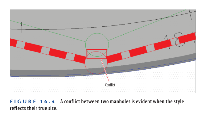
- On the Information tab, set the style to C-SSWR – Outline, then click OK.
- This style uses the actual 3D outline of the part, revealing that the manhole is larger than its symbol suggests.
- Press Esc to deselect. Now, click the storm manhole (with a “D” inside a circle), and open Structure Properties again.
- Change the style to C-STRM – Outline and click OK, then press Esc.
- With both manholes displayed at true size, a clear conflict appears (Figure 16.4).
- In the left viewport, pan north to the start of Jordan Court, where the new water line connects to the existing one. Select the tee fitting and two elbow fittings near the connection.
- Right-click and choose Properties. Change the Style to Water 3D.
- Press Esc to clear the previous selection but keep the Properties window open. Pan northeast to the opposite corner of the Jordan Court – Emerson Road intersection, and select the storm manhole located there.
- In the Properties window, set the style to C-STRM – MH Symbol Plan & Profile.
- As the new style is applied, observe the manhole in the profile view (top-right viewport) — its shape changes slightly because the block used is not an exact dimensional match for the actual manhole.
- Save and close the drawing.
To compare your results, open the drawing named Applying Structure and Fitting Styles – Complete.dwg.
https://www.mediafire.com/file/fs6qomzubcc5w6a/Applying+Structure+and+Fitting+Styles+-+Complete.dwg/file
Watch Complete Video tutorial here for this Exercise:
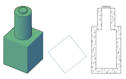
It’s Not Called 3D for Nothing
In AutoCAD® Civil 3D® 2025, pipes and structures are true 3D objects. For instance, a manhole structure often consists of complex shapes like cylinders, tapers, and eccentric sections. These 3D forms allow structures to be displayed in different ways—such as slices or outlines.
In the example image, the same structure is shown in three views: a 3D perspective (left), a plan view outline (center), and a profile view slice (right).
Using 3D representations helps improve design accuracy and ensures your structures don’t clash with other underground utilities.
Applying Pipe Styles
In AutoCAD® Civil 3D® 2025, a pipe object is simpler than a structure—it’s typically an extrusion of a circle, ellipse, or rectangle. However, its graphical representation is divided into multiple components, each of which can be styled individually.
Figure 16.5 displays a pipe and its various parts in profile view, highlighting how different styles can be applied to customize its appearance.
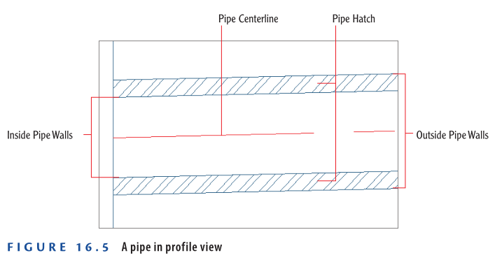
Using Pipe Styles to Control Pipe Display
In AutoCAD® Civil 3D® 2025, you can customize various pipe components using styles:
- Pipe Centerline: Control visibility, color, linetype, and width. For example, a dashed centerline set to the pipe’s inside diameter can create a striped appearance like storm pipes.
- Inside and Outside Pipe Walls: Style controls visibility and properties.
- Pipe End Line: A line across the pipe ends, customizable to extend to the inner or outer wall.
- Pipe Hatch: Hatch styles can fill the inside, outside, or between pipe walls with pattern, scale, and rotation options.
- Crossing Pipe: In profile view, pipes crossing at angles appear as ellipses. Styles manage the visibility of inner/outer walls and hatching—helpful for detecting conflicts.
While CAD managers typically create these styles, understanding their capabilities helps you request the right settings.
Exercise 16.2: Control the Display of Pipes
- Open Applying Pipe Styles.dwg which you can download from video tutorial description below.
- The left view shows a sanitary pipe crossing a storm pipe at Logan Court.
- The top right is a profile view; bottom right is a 3D view.
- In the left viewport, select the green SAN pipe. Click Pipe Properties from the ribbon.
- In the Pipe Properties dialog, go to the Information tab and set the style to C-SSWR – Double Line. Click OK.
- Press Esc to deselect.
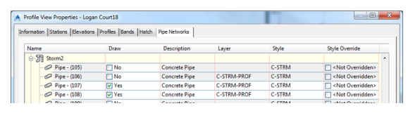
- Click inside the profile view grid (top-right viewport), then select Profile View Properties from the ribbon.
- Go to the Pipe Networks tab. Find the Storm2 network.
- Check the Style Override box for the pipe listed with Yes in the Draw column.
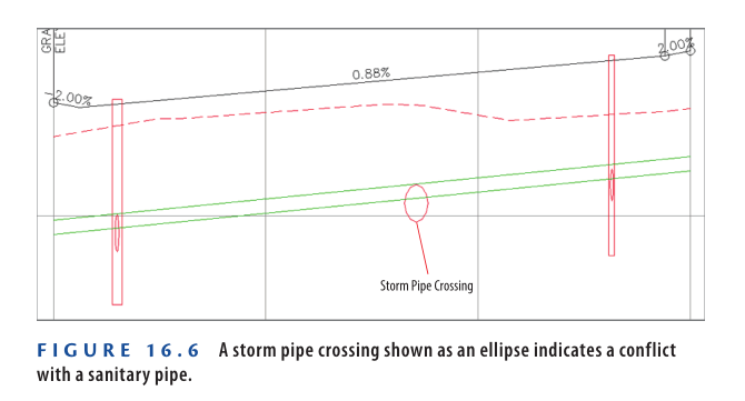
- In Pick Pipe Style, choose C-PROF-STRM – Crossing and click OK twice.
The storm pipe now appears as an ellipse at the crossing point in the profile view.
Figure 16.6 illustrates this change.
Step 7: Save and Close the Drawing
After applying the new pipe styles and observing the results in plan and profile views, save and close the drawing.
To verify your changes, open Applying Pipe Styles – Complete.dwg located in the Chapter 16 class data folder.
https://www.mediafire.com/file/h0byf3y8aowlilc/Applying+Pipe+Styles+-+Complete.dwg/file
Watch Complete video here for this exercise:
Profile View Overrides in Civil 3D 2025
The Profile View Properties dialog box includes a dedicated Pipe Networks tab. Here’s what it offers:
- Draw Column: You can toggle the visibility of any pipe or structure in the profile view by checking/unchecking this box.
- Style Override Column: Allows you to apply a unique display style to any pipe or structure specifically within that profile view.
✅ Use Cases:
- Crossing Style in One View, Normal in Another: For instance, you may want a pipe to appear as a crossing ellipse in one profile view (using
C-PROF-STRM – Crossing) while maintaining a standard style elsewhere. - Clear Communication: Style overrides help improve clarity in documentation, especially when multiple utilities cross or overlap.
Annotating Pipe Networks in Plan View
For a pipe system to function properly, it must be installed with a high degree of accuracy. To achieve this, detailed information must be conveyed to the contractor installing the pipes and structures in the field. The most common method is to add text to your drawing. By using stations and offsets, you provide the horizontal location of each structure, and with slopes and elevations, you dictate the depth of each pipe and the slope necessary for proper water flow. These values are usually expressed to the nearest hundredth of a foot or thousandth of a meter. It’s remarkable to think that a trench can be excavated and a heavy concrete pipe laid with such precision, but it happens every day.
Up until now, you have worked with functions that create pipes and structures, edit their design, and control their graphical appearance in the drawing. In the following sections, you’ll learn how to annotate your design, which is arguably even more important than the design itself. While the lines and symbols provide a useful representation of the design, the stations, offsets, elevations, slopes, and other annotations allow for precise measurements that locate and orient each pipe and structure in the field.
Renaming Pipes and Structures
Many pipe network designs involve numerous pipes and structures. For this reason, it’s considered good practice to have a naming and/or numbering system to keep track of these components. Before labeling pipes and structures, you should take time to rename them according to your chosen system.
Exercise 16.3: Rename Pipes and Structures
In this exercise, you’ll perform some “bookkeeping” by renaming the pipes and structures in the Storm1 network following a numerical sequence.
- Open the drawing named “Renaming Pipes and Structures.dwg” which you can download from video tutorial description below.
- In the viewport on the left, click the inlet at station 5+50 (0+170) on the east side of Jordan Court. Right-click and select Properties.
- In the Properties window, change the name to INLET-01. Press Esc to clear the selection, then click the inlet across the street from INLET-01.
- In the Properties window, change the name to INLET-02. Press Esc to clear the selection.
- Click the pipe between INLET-01 and INLET-02, and change its name to STM-01.
- Change the name of the pipe exiting INLET-02 to the north to STM-02.
- Change the name of the manhole near station 3+50 (0+110) to STMH-01.
- Continue working along the pipe network, renaming the inlets, pipes, and manholes according to this sequence. When you reach the final structure, the endwall, name it ENDWALL-01.
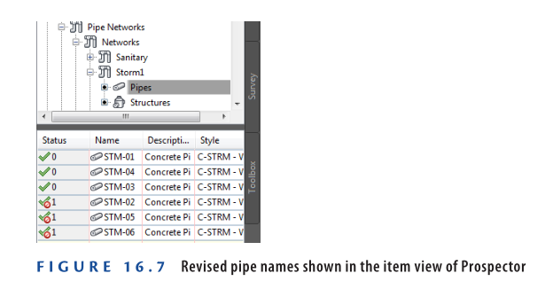
- In Prospector, expand Pipe Networks ➢ Networks ➢ Storm1. Under Storm1, click Pipes.
In the item view at the bottom of Prospector, the pipe names should all be updated as shown in Figure 16.7, although they may appear in a different order.
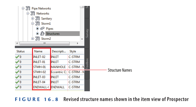
- Under Storm1, click Structures.
In the item view at the bottom of Prospector, the values listed in the Name column should match Figure 16.8.
- Save and close the drawing.
You can view the results of successfully completing this exercise by opening
Renaming Pipes and Structures – Complete.dwg.
https://www.mediafire.com/file/qqvsptt9o9twnwx/Renaming+Pipes+And+Structures+-+Complete.dwg/file
Watch complete Video tutorial for this Exercise:
Creating Labels in Plan View
To create labels in plan view, use the Add Labels command. You can apply labels individually or to the entire network at once. Once added, you may need to reposition the labels to clear areas in the drawing for better readability.
Exercise 16.4: Create Plan View Labels
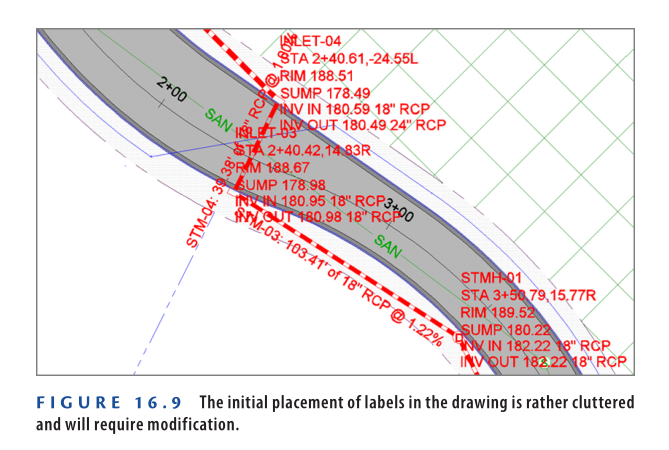
In this exercise, you’ll add all plan view labels at once for the Storm1 network. The initial result will appear cluttered, but adjustments will be made in the next step.
- Open the drawing named Creating Labels in Plan View.dwg which you can download from video tutorial description below.
- Go to the Annotate tab on the ribbon and click Add Labels.
- In the Add Labels dialog box, set the following:
- Feature: Pipe Network
- Label Type: Entire Network Plan
- Pipe Label Style: C-STRM – Pipe Data (One Line)
- Structure Label Style: C-STRM – Structure Data
- Click Add
- Click on any pipe or structure within the Storm1 network near the entrance to Jordan Court.
Labels will be applied to every pipe and structure, resulting in a cluttered appearance (refer to Figure 16.9).
- Save and close the drawing.
You can review the completed version by opening Creating Labels in Plan View – Complete.dwg.
https://www.mediafire.com/file/xz8sojy4kga90so/Creating+Labels+in+Plan+View+-+Complete.dwg/file
Watch complete video tutorial here for this Exercise:
Editing Labels in Plan View
Once pipe network labels are added, they often need adjustment for clarity and presentation. This includes repositioning labels using grips and changing their styles for better readability.
Exercise 16.5: Edit Plan View Labels
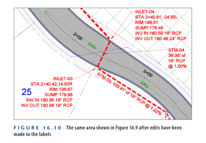
In this exercise, you’ll resolve the cluttered appearance from Exercise 16.4 by grip-editing labels and applying different styles.
- Open the drawing named Editing Labels in Plan View.dwg which you can download from video tutorial below.
- In the left viewport, zoom in to INLET-01 near station 5+50 (0+170) on the east side of Jordan Court. Select its label and drag the square grip to a clear area.
- Repeat the process for INLET-02, across from INLET-01.
- Press Esc, then click the pipe label for STM-01. Right-click and choose Properties.
- In the Properties window, set Pipe Label Style to C-STRM – Pipe Data (Stacked).
- Drag the label to a clear area using the square grip.
- Similarly, move the labels for STMH-01, INLET-03, and INLET-04 to open areas.
- Change the label style of STM-04 to C-STRM – Pipe Data (Stacked) and move it to a clear location.
- Press Esc, then click the STM-05 label. On the ribbon, click Flip Label.
- Drag the diamond-shaped grip of the STM-05 label along the pipe to observe its movement.
- Reposition remaining structure labels and change STM-06 label style to C-STRM – Pipe Data (Stacked).
After these edits, the labels become more organized and easier to read, improving the clarity of your design.
- Save and close the drawing.
You can view the finished result by opening Editing Labels in Plan View – Complete.dwg.
https://www.mediafire.com/file/cpzq0ckbtuxaxd8/Editing+Labels+in+Plan+View+-+Complete.dwg/file
Watch Complete video tutorial here for this exercise:
Annotating Pipe Networks in Profile View
Profile view holds equal importance to plan view in showcasing design details and conveying vital text and numeric information. For this reason, profile labels are often required alongside plan labels. Commonly, the same information displayed in plan view is duplicated in profile view, ensuring that contractors or reviewers can access all necessary data without switching between sheets.
There is no need to rename pipes and structures specifically for the profile view if they have already been named in the plan view. This is because both views reference the same objects from different perspectives. Renaming an object in plan view automatically reflects in profile view since they represent a single entity.
Creating Labels in Profile View
To add pipe network labels in profile view, use the Add Labels dialog box. You can either use the Entire Network Profile option to label everything at once or the Single Part Profile option for labeling individual parts.
Exercise 16.6: Create Profile View Labels
In this exercise, you’ll add pipe and structure labels to the profile view.
- Open the drawing named Creating Labels in Profile View.dwg which you can download from video tutorial description below.
- On the Annotate tab, click Add Labels.
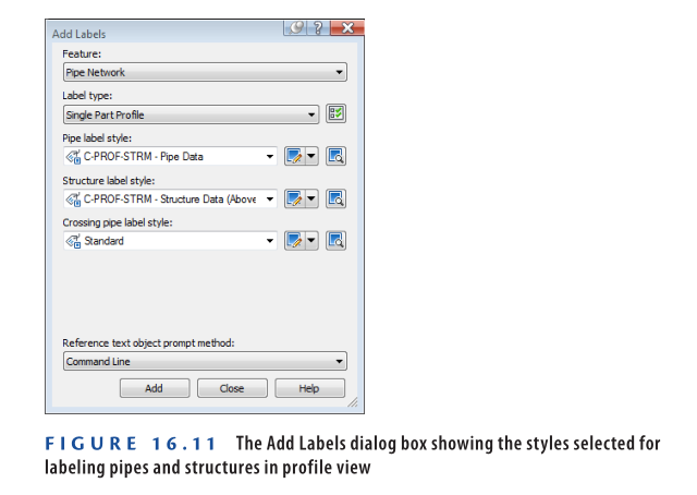
- In the Add Labels dialog box, apply the following settings:
a. For Feature, select Pipe Network.
b. For Label Type, choose Single Part Profile.
c. For Pipe Label Style, select C-PROF-STRM – Pipe Data.
d. For Structure Label Style, select C-PROF-STRM – Structure Data (Above).
e. Click Add.
Figure 16.11 shows the Add Labels dialog box with these settings.
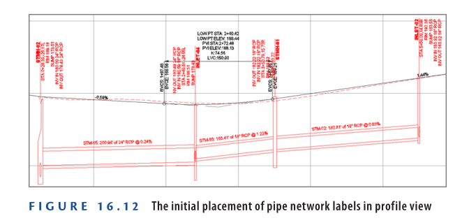
- Click the first and last structures in the upper-right profile view.
- In the Add Labels dialog box, change the Structure Label Style to C-PROF-STRM – Structure Data (Below), then click Add.
- Click the second and third structures.
The labels still appear above the structures, but the formatting differs slightly. You’ll adjust the label positions in the next exercise. - Click the three pipes in the profile view to place a label above each one.
The drawing should now resemble Figure 16.12, which shows all pipes and structures in the profile view with appropriate labels placed according to the selected styles.
- Save and close the drawing.
You can view the results of successfully completing this exercise by opening
Creating Labels in Profile View – Complete.dwg.
https://www.mediafire.com/file/vbrluxzhn0fate9/Creating+Labels+in+Profile+View+-+Complete.dwg/file
Watch Complete Video tutorial here for this Exercise:
Editing Labels in Profile View
Just like in plan view, you’ll often need to adjust the placement and style of profile view labels to enhance readability. You can apply different styles for formatting and use grips to reposition the labels. Some styles also include an extra grip at the dimension anchor, which can be moved vertically only. This helps maintain horizontal alignment while improving clarity. The dimension anchor can also be configured to relate to a specific part or the profile view grid, giving you more flexibility in label placement.
Exercise 16.7: Edit Profile View Labels
In this exercise, you’ll refine the labels created earlier to improve their visibility.
- Open the drawing named Editing Labels in Profile View.dwg which you can download from video description below.
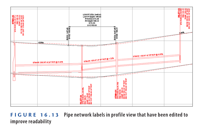
- In the upper-right viewport, select the first structure label (STMH-02), then drag the square grip at the top of the label upward to a clear space.
- Press Esc to deselect. Now click the second structure label (INLET-04), and on the ribbon, click Label Properties.
- In the Properties window, set Dimension Anchor Option to Below. The label flips downward but still overlaps the structure.
- Use the square grip at the top of the label, enable Ortho Mode, and move the label downward until the line ends at the bottom of the structure.
- Repeat steps 3–5 for the third structure label (INLET-05).
With these edits, the label positioning in profile view is much clearer. Compare your final result to Figure 16.13, and note the improvements over the original label placement shown in Figure 16.12.
- Save and close the drawing.
You can view the results of successfully completing this exercise by opening Editing Labels in Profile View – Complete.dwg.
https://www.mediafire.com/file/ee3rp0y5nvqs4sv/Editing+Labels+in+Profile+View+-+Complete.dwg/file
Watch Complete video tutorial here for this Exercise:
Creating Pipe Network Tables
As covered in earlier chapters, tables are a powerful tool for presenting design data in a clear, organized manner. Their key benefit lies in readability, though they can require readers to check both the drawing for visuals and the table for data. This is why tables are best used when adding too much text directly to the drawing would cause clutter.
Previously, parcel and alignment tables required tag labels to generate the table. In contrast, pipe network tables connect directly to pipes and structures without needing such tags. However, it’s still recommended to label each pipe and structure so readers can easily relate the drawing to the table data.
Exercise 16.8: Create a Pipe Network Table
In this exercise, you’ll insert a pipe network table and add corresponding labels in the drawing for clarity.
- Open the drawing named Creating Pipe Network Tables.dwg which you can download from video tutorial description below.
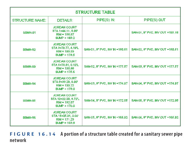
- On the Annotate tab of the ribbon, click Add Tables ➢ Pipe Network ➢ Add Structure. This will open the Structure Table Creation dialog box.
- Set the Table Style to C-SSWR – Structure & Pipe Data.
- Ensure that By Network is selected, and under Select Network, choose Sanitary. Click OK.
- Click a point in the left viewport where there is open space.
The table is placed in the drawing. Zoom in to examine the information it presents, as shown in Figure 16.14.
- On the Annotate tab of the ribbon, click Add Labels.
- In the Add Labels dialog box, set the following:
a. Feature: Pipe Network
b. Label Type: Entire Network Plan
c. Pipe Label Style: C-SSWR – Name Only
d. Structure Label Style: C-SSWR – Name Only
e. Click Add. - Click any sanitary pipe or structure in the drawing to apply the labels.
- For each sanitary sewer manhole, click the label and drag it using the square grip to a clear area of the drawing.
- For each sanitary sewer pipe label, use the diamond-shaped grip to slide it to a clear spot. If that’s not feasible, use the square grip to move it away from overlapping text or linework.
- Save and close the drawing.
You can compare your results with the completed version by opening Creating Pipe Network Tables – Complete.dwg.
https://www.mediafire.com/file/m5msvqtd18w4ghr/Creating+Pipe+Network+Tables+-+Complete.dwg/file
Watch Complete Video here for this Exercise:
Now You Know
Now that you have completed this chapter, you can modify the appearance of structures and pipes by applying different styles in Civil 3D 2025. You’ve understood the value of organized data management when working with pipe networks, including renaming pipes and structures using a logical naming convention. You can annotate pipes and structures effectively, both in plan and profile views, ensuring clarity in your drawings. Additionally, you can generate tables that display pipe network data and create labels that connect the table information with the corresponding elements in the drawing. You’re now equipped to display and annotate pipes in a real-world production environment.