Understanding Gravity Pipe Networks
Pipe network design in AutoCAD® Civil 3D® 2025 is categorized into two types: gravity networks and pressure networks. These systems serve different purposes, so their design and construction vary significantly. This chapter focuses on gravity pipe network design.
To design an effective gravity pipe network, the following must be ensured:
▶ Pipes must have a slope to allow water flow.
▶ Pipes must be sized to carry the expected water volume.
▶ Pipes must be deep enough to avoid damage from freezing or surface activity.
▶ Pipes must not be too deep to make installation excessively costly.
▶ Structures must provide access for maintenance.
▶ In stormwater systems, structures must allow surface water entry.
These factors are related to two main design components in Civil 3D: structures and pipes. This chapter covers both elements and their interaction within a pipe network.
Understanding Structures
Structures provide underground pipe access either for maintenance or for collecting surface runoff. In stormwater systems, catch basins or inlets are positioned to gather runoff efficiently. Water flows through grates into chambers and then out through pipes. For other systems like sanitary sewers, manholes and cleanouts are used for access and direction changes. Their placement is a critical part of pipe network design and follows specific planning.
Understanding Pipes
Pipes transport water to its destination. Stormwater pipes may direct treated runoff to a nearby stream, while sanitary sewer pipes may connect to treatment facilities miles away. Since gravity drives the water flow, all pipes must slope downward. Balancing slope, depth, and pipe size is essential. Pipe sizing is typically handled by qualified professionals and falls outside the scope of this book.
Exploring the Pipe Network
AutoCAD Civil 3D 2025 allows creation of structure and pipe objects and defines their relationships with surfaces, alignments, and profiles. Together, these components form a Civil 3D pipe network. In Figure 14.1, a plan view, profile view, and 3D view of pipes and structures are shown.

Each component of a pipe network is shown in Prospector. From here, you can right-click each component to access various context commands for it. You can also use the item view at the bottom of Prospector to edit information about each component. Figure 14.2 shows the contents of a pipe network in Prospector.

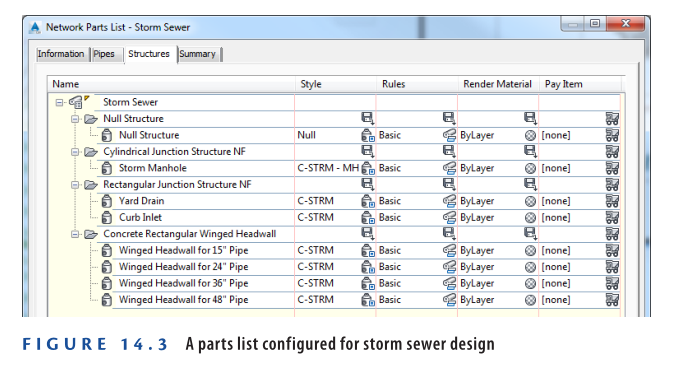
Understanding Parts Lists
The shape, size, and behavior of each pipe network component in AutoCAD Civil 3D 2025 are defined by the part it uses. These parts are organized in a parts list, which acts like a library for selecting components in your pipe network. Most organizations maintain multiple parts lists tailored for specific systems such as storm, sanitary, or water. These parts lists can be embedded in a template file, making them accessible in every new drawing based on that template. Figure 14.3 illustrates a basic parts list typically used for storm sewer design.
Creating Gravity Pipe Networks
In AutoCAD Civil 3D 2025, gravity pipe networks can be created in two main ways. One method involves converting existing objects like lines, arcs, or polylines into a pipe network all at once. The second method is by manually laying out pipes and structures one by one, known as creating a pipe network by layout.
Creating a Pipe Network from Objects
You can begin by sketching your network using basic AutoCAD entities. Civil 3D’s Create Pipe Network From Object command allows you to convert these into a complete pipe network. This command also works with alignments and feature lines. A limitation of this method is that the same parts are applied to all pipes and structures in the network.
Exercise 14.1: Create a Pipe Network from Objects
- Open the file: Creating Pipe Networks From Objects.dwg which you can download from Video description below.
- In the left viewport, zoom in to the start of the Jordan Court alignment at the north. Locate the bold green polyline labeled SAN.
- Go to Home tab > Pipe Network > Create Pipe Network From Object.
- Click the SAN polyline, then press Enter to confirm flow direction.
- In the dialog:
a. Set Network Name to Sanitary.
b. Choose Sanitary Sewer as the parts list.
c. Set Surface Name to Road FG.
d. Select Jordan Court for Alignment Name.
e. Check Erase Existing Entity.
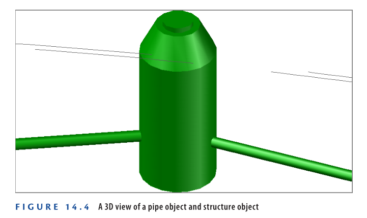
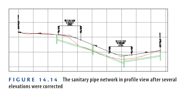
f. Click OK. - In the bottom-right viewport, zoom to a manhole. The plan view may appear basic, but you’ll now see actual 3D pipe and structure objects (see Figure 14.4).
- In the left viewport, pan south until you can see Madison Lane.
- On the Home tab, go to Pipe Network ➢ Create Pipe Network From Object.
- Click the green polyline along Madison Lane.
- Press Enter to confirm the flow direction shown by the black arrows.
- In the dialog box:
a. Set Network Name to Sanitary-2.
b. Select Sanitary Sewer as the parts list.
c. Set Surface Name to Road FG.
d. Choose Madison Lane for the alignment.
e. Check Erase Existing Entity.
f. Click OK. - Repeat steps 8–11 for the last polyline starting from Madison Lane cul-de-sac.
- Use Sanitary-3 as the network name. - Use the lower-right viewport to zoom and inspect the pipes and structures in 3D.
- Save and close the drawing.
✅ To compare your work, open Creating Pipe Networks from Objects – Complete.dwg.
https://www.mediafire.com/file/e6pend4zhnthz39/Creating+Pipe+Networks+From+Objects+-+Complete.dwg/file
Watch Complete video here for this Exercise:
Creating a Pipe Network by Layout
If no sketch exists or you want full control during design, use Pipe Network by Layout.
This method uses the Pipe Network Creation Tools command. Once launched, it opens the Network Layout Tools toolbar (shown in Figure 14.5), which resembles layout tools used for alignments and profiles.

Using the Network Layout Tools Toolbar
From the Network Layout Tools toolbar, you can:
- Select pipes and structures from a designated parts list.
- Use toolbar commands to insert those parts into your drawing.
- Switch parts anytime during layout, allowing flexibility in type and size selection.
- As you draw, connection icons appear next to your cursor to show when parts are being connected correctly.
🔶 For example, in Figure 14.6, when a pipe is being drawn between two inlets, a yellow icon shows up—this indicates the pipe will automatically connect to the inlet when clicked.

Exercise 14.2: Create a Pipe Network by Layout
Follow these steps to design part of the stormwater system using the Pipe Network Creation Tools in Civil 3D:
Step-by-Step Instructions
- Open the Drawing
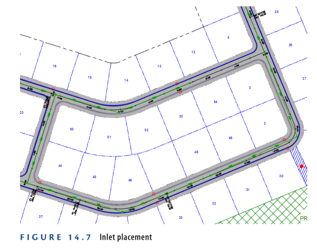
Open Creating Pipe Networks By Layout.dwg which you can download from video description below. 🔍 Red circles in the drawing show inlet locations. You’ll see some are placed at low points (as marked on the alignment) to prevent overloading. Additional inlets are placed between low and high points to manage runoff efficiently. - Access Pipe Network Creation Tools
On the Home tab of the ribbon, click:
➤ Pipe Network ➝ Pipe Network Creation Tools - Fill in the Pipe Network Info
In the Create Pipe Network dialog box:
a. Network Name:Storm1
b. Network Parts List:Storm Sewer
c. Surface Name:Road FG
d. Alignment Name:Jordan Court
e. Click OK to proceed.
- You’re prompted to specify a structure insertion point. In the left
viewport, zoom in to the red circles at Jordan Court station 5+50
(0+170). On the Network Layout Tools toolbar, do the following:
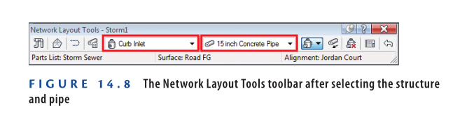
▶ ▶ To choose a structure, select Rectangular Junction Structure
NF (SI) ➢ Curb Inlet from the first drop-down list.
▶ ▶ To choose a pipe, select Concrete Pipe (SI) ➢ 15 Inch (400mm)
Concrete Pipe from the second drop-down list.
The Network Layout Tools toolbar should appear as shown in
Figure 14.8.
- Right-click the Osnap icon at the bottom of the screen, and then
click Object Snap Settings.
- On the Object Snap tab of the Drafting Settings dialog box, do the
following:
a. Check the box next to Object Snap On (F3).
b. Click Clear All.
c. Check the box next to Center.
d. Click OK. - Click the center of the red circle to the east of station 5+50 (0+170).
- Click the center of the red circle to the west of station 5+50 (0+170).
- Pan northward until you can see the two red circles at the low
point of station 2+40.42 (0+073.28). Click the circle to the south
of the road. - On the Network Layout Tools toolbar, choose the pipe Concrete Pipe
(SI) ➢ 18 Inch (450mm) Concrete Pipe. - Click the center of the red circle located north of station 2+40.42
(0+073.28). - On the Network Layout Tools toolbar, do the following:
a. Choose the structure Cylindrical Junction Structure NF (SI) ➢
Storm Manhole.
b. Choose the pipe Concrete Pipe (SI) ➢ 24 Inch (600mm)
Concrete Pipe. - Click the red circle located at the western corner of the common area.
- On the Network Layout Tools toolbar, choose a structure of Concrete
Rectangular Winged Headwall (SI) ➢ Winged Headwall for 24″
(600mm) Pipe. - Click the red circle on the opposite side of Emerson Road.
- Press Esc to end the command.
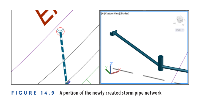
You have created a storm sewer network, which discharges at a
location across Emerson Road (see Figure 14.9).
- Save and close the drawing.
You can view the results of successfully completing this exercise by opening
Creating Pipe Networks By Layout – Complete.dwg.
https://www.mediafire.com/file/u49dr0a961ghxjn/Creating+Pipe+Networks+By+Layout+-+Complete.dwg/file
Watch Complete Video here for this Exercise:
Drawing a Pipe Network in a Profile View
Viewing a pipe network in profile view is essential for accurate design. The depths, slopes, and elevations of underground pipe systems are just as important as their horizontal layout in plan view. AutoCAD Civil 3D 2025 allows you to display pipe networks in profile view, providing the best way to review and edit the vertical alignment of the design. Using the Draw Parts In Profile command, you can display the entire network or selected components in a profile view. The pipes and structures shown in plan view will appear the same in the profile view. Any updates to the network will reflect in both views.
Exercise 14.3: Draw a Pipe Network in Profile View
In this exercise, you’ll use the Draw Parts In Profile command to display the storm network in a profile view.
- Open the drawing named Drawing Pipe Networks in Profile View.dwg which you can download from video description below.
- In the left viewport, select the new storm manhole near the western corner of the Common Area, then click Draw Parts In Profile on the ribbon.
- In the top-right viewport, click a grid line of the Jordan Court profile view. The manhole will appear in the profile. Press Esc to clear the selection.
- Click the pipe connecting from the southeast to the manhole.
- Click Draw Parts In Profile again, and then click the grid of the Jordan Court profile view.
- Repeat steps 2 and 3 for the inlet located north of station 2+40.42 (0+073.28).
- Repeat steps 2 and 3 for the pipe starting at station 2+40.42 (0+073.28) and ending at station 5+50 (0+170).
- Repeat steps 2 and 3 for the inlet west of station 5+50 (0+170).
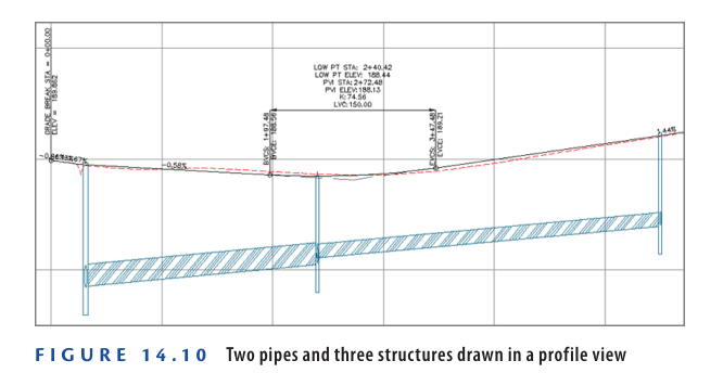
Now the profile view displays two pipes and three structures, as shown in Figure 14.10.
- Save and close the drawing.
You can view the results of successfully completing this exercise by opening
Drawing Pipe Networks in Profile View – Complete.dwg.
https://www.mediafire.com/file/gwjy71xr0z8s84y/Drawing+Pipe+Networks+In+Profile+View.dwg/file
Watch Complete Video here for this Exercise:
Editing Gravity Pipe Networks
As you might expect, the tools in Civil 3D 2025 for editing gravity pipe networks are more advanced than those for creating them. The ideal approach is to start with a basic layout and then refine the design using editing tools. Civil 3D 2025 offers multiple ways to edit pipe networks, grouped into four categories: grips, editing tools, properties, and Pipe Network Vistas.
Editing Pipe Networks using Grips
Grips allow for fast and simple graphical edits. Civil 3D 2025 provides specific grips for structures and pipes:
- Structure – Square Grip – Plan view: Moves the structure without rotating it. Connected pipes move with it.
- Structure – Circular Grip – Plan view: Rotates the structure without changing its position.
- Structure – Top Triangular Grip – Profile view: Changes the top elevation of the structure. Civil 3D might reset this based on surface data.
- Structure – Bottom Triangular Grip – Profile view: Changes the sump elevation, which can’t go above the lowest pipe invert.
- Pipe Midpoint – Triangle Grip – Plan view: Adjusts pipe diameter. Drag away to increase, or toward the pipe to decrease. Can also use Dynamic Input.
- Pipe Midpoint – Square Grip – Plan view: Moves the pipe without changing its slope or angle.
- Pipe Endpoint – Square Grip – Plan view: Moves one end of the pipe, keeping the other end fixed. Elevation stays the same in profile view.
- Pipe Endpoint – Triangular Grip – Plan view: Adjusts pipe length, maintaining angle and opposite end location.
- Pipe Endpoint Grips – Profile view: Adjust crown, invert, or centerline elevation without affecting horizontal location. Works with Dynamic Input.
- Pipe Midpoint – Square Grip – Profile view: Changes pipe elevation without changing slope or plan view location.
Remember, when moving a pipe’s endpoint in plan view, the connected structure doesn’t move with it. You must move it manually to avoid issues.
Exercise 14.4: Edit a Pipe Network using Grips
In this task, you’ll adjust parts of the storm network using grips.
- Open the drawing Editing Pipe Networks Using Grips.dwg which you can download from video description below.
- In the left plan view, zoom into the inlets at station 5+50 (0+170).
- Select both inlets, then click the circular grip on the east inlet.
- Click the square grip on the west inlet.
- This rotates the east inlet to match the west inlet, aligning it with the curb.
- Ensure Dynamic Input is enabled at the bottom of your screen.
- Zoom into the pipe at station 5+50 (0+170), select it, and click its triangular midpoint grip.
- Drag the grip until the dynamic input box reads 1.5 (0.450) or type it directly.
- This sets the pipe diameter to 18 inches (450mm).

- In the bottom-right viewport, zoom into the manhole near the west corner of the Common Area.
- Click on the manhole, then click the square grip at its center.
- If Osnap is off, turn it on by clicking the Osnap icon at the bottom of the screen.
- Click the center of the red circle just west of the manhole.
- This will reposition the manhole accurately using object snap.
- Switch to the top-right viewport and click the pipe farthest to the left in the Jordan Court profile view.
- Click the bottom diamond-shaped grip at the left end of the pipe.
- Zoom out until you see the dynamic input text box.
- Type 180 (54.864) and press Enter to set the invert elevation.
- Press Esc to deselect the pipe.
- Turn off Dynamic Input by clicking its icon again.
- Click the structure farthest to the left in the Jordan Court profile view.
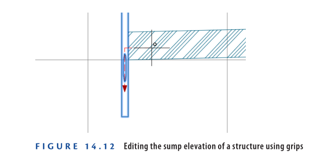
- Click the triangular grip at the bottom of the structure and drag it upward until you see a red dashed line.
- Click when the dashed line appears (this indicates a constraint related to the connecting pipe invert).
🔎 Note: The sump elevation is now raised, but Civil 3D 2025 will not allow it to go above the lowest connected pipe invert, ensuring proper drainage design.
- Save and close the drawing.
You can view the results of successfully completing this exercise by opening
Editing Pipe Networks Using Grips – Complete.dwg.
https://www.mediafire.com/file/okogilabinls5c2/Editing+Pipe+Networks+Using+Grips+-+Complete.dwg/file
Watch Complete Video here for this Exercise:
xercise 14.5: Edit Pipe Networks Using Editing Tools – Civil 3D 2025
You’ll now use the Network Layout Tools toolbar and ribbon commands to modify your storm and sanitary pipe networks.
📂 Step-by-Step Instructions:
- Open the file:
Editing Pipe Networks Using Editing Tools.dwg
(which you can download from video description below) - Select any storm pipe or structure in the drawing.
- On the ribbon, click Edit Pipe Network.
→ The Network Layout Tools toolbar will open.
- On the ribbon, click Edit Pipe Network.
- On the Network Layout Tools toolbar: a. Choose:
Structure ➝Cylindrical Junction Structure NF (SI)➝Storm Manhole
b. Expand the pipe drop-down list using the small black triangle.- Select Structures Only to avoid placing new pipes accidentally.
- Turn off Osnap by clicking the Osnap icon if it’s active.
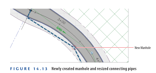
- In the plan or 3D viewport, click near the midpoint of the pipe starting at station 2+40.42 (0+073.280) and ending at station 5+50 (0+170).
→ A new manhole is inserted along the pipe. - Press Esc to cancel the current command.
- Click the new structure, then select its square center grip.
- Snap to the center of the red circle near Jordan Court station 3+50 (0+110).
- Press Esc to deselect. In the left viewport, click the pipe entering the new manhole from the south.
- On the ribbon, click Swap Part.
- In the Swap Part Size dialog box:
- Choose
Concrete Pipe (SI)➝18 Inch (450mm) Concrete Pipe - Click OK.
- Choose
- Repeat Steps 9 and 10 for the pipe exiting the manhole to the north.
- Close the Network Layout Tools toolbar, and press Esc to clear the
previous selection. Click one of the sanitary sewer pipes in the draw-
ing, and then click Merge Networks on the ribbon. - In the first dialog box, click Sanitary-2 and then click OK.
Here, you’re selecting a network that will be merged into
another. When the process is complete, a network of this name
will no longer exist. - In the second dialog box, click Sanitary and then click OK.
Here, you’re selecting the network that is having Sanitary-2
merged into it. - In Prospector, expand Pipe Networks ➢ Networks. Note that the
Sanitary-2 network is no longer listed. - Repeat steps 11–13, this time selecting Sanitary-3 in the first dialog box.
All sanitary sewer networks have been merged into one; therefore,
only one sanitary sewer network is listed in Prospector. - Save and close the drawing.
You can view the results of successfully completing this exercise by opening
Editing Pipe Networks Using Editing Tools – Complete.dwg.
https://www.mediafire.com/file/6v9h3k7xkedwei0/Editing+Pipe+Networks+Using+Editing+Tools+-+Complete.dwg/file
Watch Complete Video here for this Exercise:
Editing Pipe Networks using Properties
Most values needed for editing pipes and structures are found in their properties. There are two ways to access these: the Civil 3D method and the AutoCAD method. In the Civil 3D method, select a pipe or structure, then click Pipe Properties or Structure Properties on the ribbon. This method gives detailed editable data but must be done for each item individually. The AutoCAD method lets you use the Properties command after selecting items, allowing batch edits but with limited property access.
Exercise 14.6: Edit a Pipe Network using Properties
In this task, you’ll correct the elevation of a sanitary pipe placed too deep, noted earlier in the Madison Lane profile.
- Open the drawing named Editing Pipe Networks Using Properties.dwg which you can download from video description below.
- In the upper-right viewport, zoom to the Madison Lane profile. Look for the label reading ELEV = 180.972 (55.160) at the cul-de-sac manhole.
- In the left viewport, zoom to the manhole at Madison Lane’s cul-de-sac and click it. Select Structure Properties on the ribbon.
- In the Structure Properties dialog:
- Set Automatic Surface Adjustment to False.
- Enter 180.972 (55.160) for Insertion Rim Elevation.
- Click OK.
- Press Esc, then select the pipe starting at the cul-de-sac. Right-click and choose Properties.
- Change Start Invert Elevation to 176.972 (53.941).
- With the pipe still selected, click Pipe Properties on the ribbon.
- In the dialog, set Pipe Slope (Hold Start) to -1.5 and click OK.
- Press Esc, select the cul-de-sac manhole again, right-click, and choose Structure Properties.
- Even if it shows 2.000 (0.600), retype 2 (0.6) for Sump Depth and press Enter, then click OK.
- In the top-right viewport, zoom out to view the updated, shortened Madison Lane profile.
- Save and close the drawing.
You can view the results of successfully completing this exercise by opening
Editing Pipe Networks Using Properties – Complete.dwg.
https://www.mediafire.com/file/x7j00k0dnvekv27/Editing+Pipe+Networks+Using+Properties+-+Complete.dwg/file
Watch Complete Video here for this Exercise:
Editing Pipe Networks using the Pipe Network Vistas
The editing methods covered earlier are useful for modifying individual pipes and structures. However, if you need to view or edit the entire network or multiple parts at once, use the Pipe Network Vistas command. This opens Panorama with two tabs: Structures and Pipes. Both tabs show the full network in spreadsheet form, allowing you to view and edit properties for several components simultaneously. You’ll find the Pipe Network Vistas button near the right end of the Network Layout Tools toolbar.

Exercise 14.7: Edit a Pipe Network using the Pipe Network Vistas
In this exercise, you’ll rename certain structures and change the style of some pipes using the Pipe Network Vistas.
- Open the drawing named Editing Pipe Networks Using the Pipe Network Vistas.dwg which you can download from video description below.
- Click any storm pipe or structure, then click Edit Pipe Network on the ribbon.
- On the Network Layout Tools toolbar, click Pipe Network Vistas. This opens Panorama with Pipes and Structures tabs.
- Go to the Structures tab. While holding Ctrl, select the four rows labeled Rectangular Junction Structure NF (SI) under the Description column.

- Right-click the Description column header and choose Edit.
- Type INLET, then press Enter. All four selected descriptions update to INLET.
- In the Description column, change all instances of Cylindrical Junction Structure NF (SI) to MANHOLE.
- Update the description of the last structure to ENDWALL.
- Click the Pipes tab. Hold Shift and select the first and last rows to highlight all pipes.
- Right-click the Style column, select Edit, and in the Select Pipe Style dialog box, choose C-STRM – Walls In Profile. Click OK.
The pipe display in profile view now shows both inner and outer walls clearly.

- Save and close the drawing.
You can view the results of successfully completing this exercise by opening
Editing Pipe Networks Using the Pipe Network Vistas – Complete.dwg.
https://www.mediafire.com/file/y8br7jc7bbd1rhx/Editing+Pipe+Networks+Using+The+Pipe+Network+Vistas+-+Complete.dwg/file
Watch Complete Video here for this Exercise:
Now You Know
Now that you’ve completed this chapter, you’re prepared to create and edit gravity pipe networks in Civil 3D 2025. You can build networks using existing objects or draw them directly with the Network Layout Tools toolbar. After creating a network, you can view it in profile view and make changes using grips, editing tools, properties, or the Pipe Network Vistas.
You’re now ready to apply these skills in a real-world production environment.