Applying Parcel Styles
Parcels can represent individual lots, public spaces, road rights-of-way, easements, and more. When multiple parcel types appear in one plan, visual distinction is necessary. In Civil 3D 2025, this is efficiently managed through parcel styles.
Using Parcel Styles to Control Appearance
Parcel styles in Civil 3D 2025 allow control over parcel edge appearance and hatch patterns. Hatching can fill the entire area or form a border strip. These tools help visually separate different parcel types.
Exercise 13.1: Apply Parcel Styles
In this task, you will use various styles to distinguish legal parcel types—such as adjoiner parcels, rights-of-way, lots, open spaces, and easements.
- Open the drawing named Applying Parcel Styles.dwg which you can download from Video Description below. All parcels are set to the Standard style.
- Click the Standard : 3 label in the farm building area. On the ribbon, click Parcel Properties.
- In the Parcel Properties dialog box, under the Information tab, change Object Style to Adjoiner and click OK. The segment linetype updates to a double-dashed pattern, and the label changes to Adjoiner : 3.
- Press Esc. Click the Standard : 6 label near Madison Lane’s cul-de-sac. Right-click and choose Properties.
5. In the Properties window, change the Style to ROW. Press Esc to clear the selection. The right-of-way is now outlined with a dashed line and filled with a dot hatch pattern.
6. Use either Parcel Properties or the Properties window to change the parcels Standard : 7 and Standard : 4 in the northeast and southeast corners to the Open Space style. These now have green outlines and a green crosshatch pattern.
7. Zoom into the 90° turn on Jordan Court and locate the narrow Standard : 1 parcel.
8. Change the style of Standard : 1 to Easement. It is now hatched with diagonal stripes.
9. Select any remaining parcel labeled Standard, and set its style to Lot.
10. Open Prospector, expand Sites ➢ Lot Layout, and click Parcels to view them in the item list below.
11. Scroll right to locate the Style column. Click its heading to sort parcels by style.
12. Select the first parcel with Standard style, hold Shift, and click the last Standard parcel to select all.
13. Right-click the Style column header, choose Edit, select Lot in the dialog box, and click OK.
All selected parcels are now updated to the Lot style (refer to Figure 13.1).
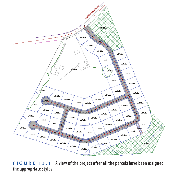
- Save and close the drawing.
You can view the results of successfully completing this exercise by opening
Applying Parcel Styles – Complete.dwg.
https://www.mediafire.com/file/o5kkkf5qx9sao5c/Applying+Parcel+Styles+-+Complete.dwg/file
Watch Complete Video here for this Exercise:
Applying Parcel Style Display Order
Adjacent parcels often share segment lines. When different styles are applied to neighboring parcels, you can manage which style is shown on shared segments using the Site Parcel Properties dialog box.
To open it, right-click Parcels in Prospector and select Properties. In the Composition tab, you’ll find the Parcel Style Display Order list (see Figure 13.2). The style listed higher takes priority for shared segments. Use the arrow buttons or drag-and-drop to reorder styles and control the display result.

Typically, certain parcel line styles should override others for visual clarity. For example, right-of-way (ROW) lines are among the most important boundaries and are usually placed at the top of the style list. This ensures their color and linetype appear uninterrupted throughout the drawing. In contrast, lot lines are less important and usually appear at the bottom of the list.
Exercise 13.2: Control Parcel Style Display Order
In this exercise, you’ll use the Parcel Style Display Order feature to manage how styles display when parcels share segments.
- Open the drawing named Applying Parcel Style Display Order.dwg which you can download from video description below.
- In Prospector, expand Sites ➢ Lot Layout.
- Right-click Parcels, and select Properties.
- In the Site Parcel Properties dialog box, go to the Composition tab and select ROW under Parcel Style Display Order.
- Use the upward-pointing arrow to move ROW to the top of the list. Click OK.
Lot 23 will now show a purple dashed line on the south and east sides, and a blue dashed line on the north and west sides. The ROW style appears “on top” of the Lot style, as defined by the Parcel Style Display Order in AutoCAD Civil 3D 2025.

6. In Prospector, right-click Parcels and select Properties.
7. Under Parcel Style Display Order, arrange the styles as follows: ROW, Adjoiner, Open Space, Lot, Property, and Basic. Click OK.
8. Zoom in and observe the areas where parcels with different styles are adjacent.
9. Save and close the drawing.
You can check your results by opening Applying Parcel Style Display Order – Complete.dwg.
https://www.mediafire.com/file/jsjvb7757ur9033/Applying+Parcel+Style+Display+Order+-+Complete.dwg/file
Watch Complete video here for this Exercise:
Applying Parcel Area Labels
The center labels of each parcel are called parcel area labels. These can show area information or other custom data. You can add them using the Add Labels command or through Parcel Properties. Like other labels, their style defines their look and content.
Exercise 13.3: Apply Parcel Area Labels
- Open Applying Parcel Area Labels.dwg which you can download from video description below.
- Click the Adjoiner : 3 label, then select Parcel Properties from the ribbon.
- In the Composition tab, set Area Selection Label Style to Existing Description And Area.
- Go to the Information tab. In the Description box, enter:
JOHN SMITHDBV 1234, PG 567
Click OK, then press Esc to clear the selection.

- Click the ROW : 6 label (in the cul-de-sac at the end of Madison Lane), then click Parcel Properties on the ribbon.
- On the Composition tab, set Area Selection Label Style to , click OK, then press Esc to clear the selection.
- Select the area labels for both green-hatched Open Space parcels, right-click, and choose Properties.
- In the Properties palette, change Parcel Area Label Style to Proposed Description And Area.
- Labels now show description and area in a different text style and color.
- Press Esc to clear selection. Go to Annotate tab > Add Labels.
- In the Add Labels dialog box:
- Feature: Parcel
- Label Type: Replace Area
- Area Label Style: Lot Number
- Click Add
- Click several parcels labeled Lot, then press Enter — labels now appear as numbers inside circles.
- Click one of the parcels, then on the ribbon click Multiple Parcel Properties.
- When prompted for a start point, click a point in a parcel with the original Lot label style.
- Then click through several adjacent parcels.
- Press Enter to finish.
- Press Enter again at the next start point prompt.
- In the Edit Parcel Properties dialog box, change Area Selection Label Style to Lot Number.
- Click the disk icon next to Lot Number.
- Click Yes to apply changes — labels will immediately update.
- Click OK to exit. Repeat steps 12–17 until all Lot parcels have the Lot Number label style.
- Save and close the drawing.
You can verify your work by opening Applying Parcel Area Labels – Complete.dwg.
https://www.mediafire.com/file/tkmf1w8utz8xile/Applying+Parcel+Area+Labels+-+Complete.dwg/file
Watch Complete Video here for this Exercise:
Creating Parcel Segment Labels
These labels show bearings, distances, and curve data for property boundaries. They’re helpful for field or legal re-creation of parcels.
Exercise 13.4: Label Parcel Segments
- Open Creating Parcel Segment Labels.dwg which you can download from video description below.
- Zoom in on Lots 32 and 33, near the center.
- On the Annotate tab, click Add Labels.
- In the Add Labels dialog:
- Feature: Parcel
- Click Add
- Click the north side of Lot 33 — a bearing and distance label will appear.
- Click the east and west sides of Lot 33 — more labels appear.
- Tip: Click near the midpoint of each line.
- Pan down to Lot 69, click the curve on its south boundary — a curve label (delta, length, radius) will be created.
- In the Add Labels dialog, set Label Type to Multiple Segment, then click Add.
Click the parcel area label for lot 32. When you’re prompted to select
a direction, press Enter to accept the default direction of clockwise.
All segments for lot 32 are labeled simultaneously. - Save and close the drawing.
You can view the results of successfully completing this exercise by opening
Creating Parcel Segment Labels – Complete.dwg.
https://www.mediafire.com/file/xww5any2q2apugu/Creating+Parcel+Segment+Labels+-+Complete.dwg/file
Watch Complete Video here for this Exercise:
Labeling Lines and Curves
You don’t need to convert lines, arcs, or polylines into parcel segments to label them in Civil 3D. You can label these basic AutoCAD entities directly using the Add Labels command.
How to Label Lines and Curves
- Go to the Annotate tab on the ribbon.
- Click Add Labels.
- In the Add Labels dialog box:
- For Feature, select Line and Curve.
- Choose your desired Label Type (e.g., Single Segment, Multiple Segments, etc.).
- Pick a Label Style that fits your needs (bearing-distance, curve data, etc.).
- Click Add.
- Click on the line or curve you want to label in your drawing.
- Labels will appear at the point where you click.
Curve Data – Key Elements
When labeling curves, Civil 3D can show various geometric values. The most commonly used curve data includes:
- Delta (Δ) – The central angle of the curve
- Length (L) – The arc length of the curve
- Radius (R) – The radius of the arc
- Chord – A straight line between the start and end of the arc
- Chord Bearing – The direction of the chord
- Tangent Length – The distance from the Point of Curvature (PC) or Point of Tangency (PT) to the Point of Intersection (PI)
- Central Angle (Δ) – The angle subtended by the arc at the center of the circle
These values can be shown using different Label Styles available in Civil 3D.

- ▶ Length: Distance measured along the curve’s arc.
- ▶ Radius: Distance from the center of the curve to a point on it.
- ▶ Chord: A straight line from the curve’s start to end point.
- ▶ Delta: Angle between the tangents at the beginning and end of the curve.
- ▶ Tangent: Distance from Point of Curvature (PC) to Point of Intersection (PI), or Point of Tangency (PT) to PI.
Depending on local drafting standards, you may combine several of these properties to properly annotate a curve. Often, multiple curve labels are used to provide sufficient detail for reconstructing the curve.
Editing Parcel Segment Labels
After placing parcel segment labels, you often need to adjust their position, style, orientation, and other settings to improve drawing clarity and meet presentation standards.
Applying Segment Label Styles
Parcel segment label styles control:
- Appearance
- Content (e.g., bearing, distance, curve data)
- Text orientation and formatting
You can apply different styles based on whether the segment is proposed or existing, or based on local requirements.
Exercise: Apply Parcel Segment Label Styles
- Open
Applying Parcel Segment Label Styles.dwg. which you can download from video description below. - Zoom to the west side of the project.
- Select the label on the west side of the John Smith property.
- On the ribbon, click Label Properties.
- In Properties, change Line Label Style to
(Span) Bearing And Distance With Crows Feet [Existing]. - On the Annotate tab, click Add Labels.
- Set:
- Feature: Parcel
- Label Type: Single Segment
- Line Label Style: Distance [Existing]
- Click the same west side segment to apply a new distance-only label.
- Pan to view lots 36, 37, 60, and 59.
- Select these labels → Label Properties → Change Line Label Style to Distance.
- Save and close the drawing.
You can compare your result with Applying Parcel Segment Label Styles - Complete.dwg.
https://www.mediafire.com/file/9r4xn1zmluullkx/Applying+Parcel+Segment+Label+Styles+-+Complete.dwg/file
Watch Complete video here for this Exercise:
Editing Parcel Segment Labels Graphically
Civil 3D 2025 provides intuitive tools for graphical label adjustments:
- Grips for repositioning labels
- Flip Label: Move label to the opposite side
- Reverse Label: Switch direction (e.g., NE to SW)
- Dragged State: Automatically moves label with a leader line when space is limited
Exercise: Edit Parcel Segment Labels Graphically
- Open
Editing Labels Graphically.dwg. which you can download from video description below. - Select the label on the west side of lot 68 → Label Properties → Change style to Bearing.
- Click Flip Label to place it on the opposite side.
- Use the grip to drag the label between lots 68 and 62.
- Click Reverse Label to update bearing direction.
- Repeat for lot 62:
- Change style to Distance
- Flip label to the inside of the lot
- Use Add Labels to add a new Distance label to the west side of lot 68 and flip it inside.
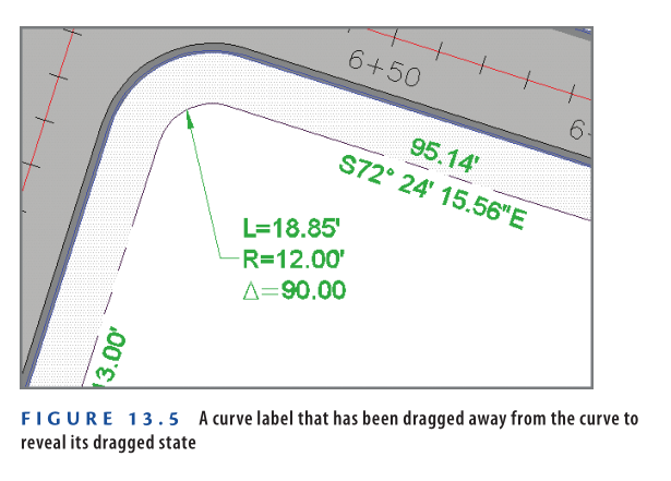
- Select the curve label at the NW corner of lot 68 → Drag grip to place the label in an open space → Civil 3D automatically adds a leader(see Figure 13.5).
9: Continue moving, flipping, and reversing labels to improve the read-ability of the drawing and remove redundant bearings. Assign new styles where applicable.
10: Save and close the drawing.
You can view the results of successfully completing this exercise by opening
Editing Labels Graphically – Complete.dwg.
https://www.mediafire.com/file/ewdlt2eawpa0iw1/Editing+Labels+Graphically+-+Complete.dwg/file
Watch Complete video here for this Exercise:
Creating Parcel Tables
Property drawings can become cluttered with numerous labels for areas, bearings, distances, and curve dimensions. To reduce clutter, this data can be placed in a table. Line and curve labels may be replaced with simplified tags like L1, L2, etc. This makes the drawing cleaner and easier to interpret. However, users must refer back and forth between the drawing and the table. While direct labels can make drawings easier to read, some complex layouts require tables instead.
Creating Area Tables
Area tables can display parcel information clearly, depending on the chosen table style. Before creating an area table, it’s often necessary to renumber the lots using the Renumber/Rename tool on the ribbon.
Exercise 13.7: Create an Area Table
In this exercise, you’ll renumber the lots and create an area table showing each lot number and area.
- Open Creating An Area Table.dwg which you can download from video description.
- Select a lot number label and click Renumber/Rename on the ribbon.
- In the Renumber/Rename Parcels dialog, check Use Name Template In Parcel Style, then click OK.
- When prompted for a start point, click near the center of lot 24. Follow the red arrows in Figure 13.6 to select parcels in the correct order.
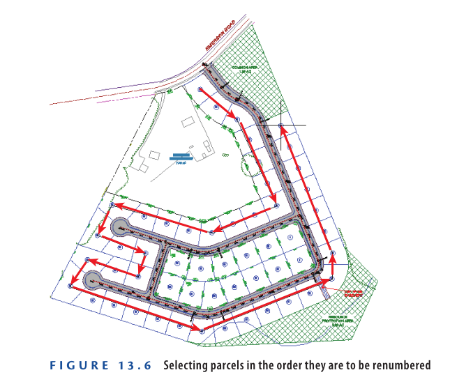
5. Press Enter twice to finish the command and update the numbers. The numbering should now start at 1 and end at 40 in the selected path.
6. Press Esc to clear the selection. Zoom into the central lots of the project. Click one lot label, then click Renumber/Rename on the ribbon.
7. In the Renumber/Rename Parcels dialog, check Use Name Template In Parcel Style and click OK.
8. Draw lines starting at lot 68, proceed clockwise, and end at lot 62. Press Enter twice to finish.
9. Press Esc to clear selection. Click a lot label and then go to Add Tables ➢ Add Area on the ribbon.
10. In the Table Creation dialog:
a. Set Table Style to Area Only.
b. Under Select By Label Or Style, check the Apply box across from Lot Number.
c. Click OK.
11. Click an open area in the drawing to insert the area tables.
12. Save and close the drawing. To see the completed result, open Creating an Area Table – Complete.dwg.
https://www.mediafire.com/file/x6zzvwkalhdytax/Creating+An+Area+Table+-+Complete.dwg/file
Watch Complete Video here for this Exercise:
Creating Parcel Segment Tables
Creating segment tables works like area tables. You can select segments by style or manually. Labels are converted into tags (e.g., C1, C2), and can be renumbered using the Renumber Tags tool. Segment tables can be for line, curve, or segment (both line and curve).
Exercise 13.8: Create a Parcel Segment Table
- Open Creating A Segment Table.dwg Which you can download from Video Descritpion below.
- On the Annotate tab, click Add Tables ➢ Parcel ➢ Add Curve.
- In the Table Creation dialog:
a. Set Table Style to Length Radius & Delta.
b. Under Label Style Name, check the Apply box across from Parcel Curve: Delta Over Length And Radius.
c. Click OK. - Click an open space in the drawing to insert the table.
- Click the curve label at lot 41’s northwest corner, and drag the circular grip to reset the label on the curve.
- With the label still selected, click Renumber Tags on the ribbon — it will now display C1.
- Press Esc, then click the next curve label to the east and click Renumber Tags — it will now show C2.
- Continue clockwise, selecting curve labels and renumbering tags until all are updated. Use Esc between each.
- Go to Annotate ➢ Add Labels.
- In the Add Labels dialog:
a. Choose Parcel as the feature.
b. Set label type to Multiple Segment, then click Add. - Click on the lot 17 label and press Enter to accept clockwise direction. Repeat for lot 18. New labels will appear.
- Renumber these new curve tags to maintain the sequence.
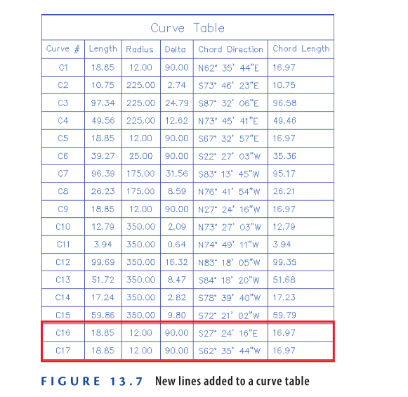
- Click the curve table, then click Add Items on the ribbon. In the Add Selection dialog, check the box across from Parcel Curve: Delta Over Length And Radius. Click OK.
- Pan to the table and verify that new data was added successfully (see Figure 13.7).
- Save and close the drawing.
You can view the results of successfully completing this exercise by opening
Creating a Segment Table – Complete.dwg.
https://www.mediafire.com/file/1wlssk7sloaf7af/Creating+A+Segment+Table+-+Complete.dwg/file
Watch Complete Video here for this Exercise:
Now You Know
Now that you have completed this exercise, you’re ready to work with parcel styles and annotations in Civil 3D 2025. You’ve learned how to apply styles to make parcels display differently and how to use the Parcel Style Display Order to manage adjacent parcels sharing common segments. You can now apply and customize area and segment labels. You also know how to renumber parcels and segment label tags and generate tables displaying their data. You’re now prepared to manage parcel display and annotation in a real-world project environment.