Understanding Parcels
In land development, projects often require purchasing, merging, or subdividing land. Even when this is not needed, it is crucial to accurately represent property boundaries in design drawings and mark them in the field to prevent encroachment. Additionally, determining the location of rights-of-way and easements, whether existing or proposed, is essential. AutoCAD Civil 3D 2025 provides tools for efficiently creating, analyzing, and displaying legal boundaries through parcel objects and related commands.
Understanding Parcel Objects
Like other Civil 3D features, parcels utilize specialized objects to streamline creation and modification. Parcel segments, which represent the sides of a parcel using lines and curves, are fundamental to this process. These segments can be drawn using a dedicated toolbar or converted from existing lines, arcs, and polylines. Each parcel segment must be assigned to a site so that Civil 3D recognizes their interactions. When parcel segments within the same site form a closed shape, Civil 3D automatically generates a parcel object. This method ensures efficient parcel creation while maintaining accuracy.

Any changes made to the fundamental objects that form a parcel will automatically update the parcel itself. This is particularly noticeable when parcels are labeled with details such as area, bearing, and distance.
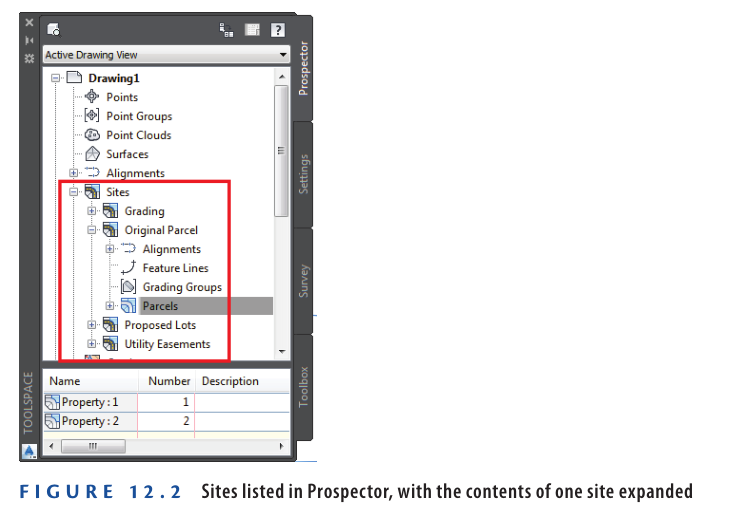
Understanding Sites
Grouping objects within the same site allows Civil 3D to recognize their interactions. To prevent objects from interacting, they can be assigned to different sites. Sites are managed within the Prospector and can be created as needed for a given drawing.
Parcel Creation and Interaction
When parcel segments within the same site form closed shapes, Civil 3D automatically converts them into parcels. Other objects, such as alignments, feature lines, grading groups, and survey figures, can also exist within sites and interact with parcels.
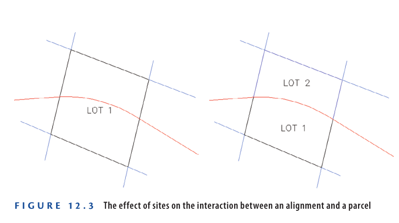
For example, if an alignment crosses a parcel within the same site, it will automatically subdivide the parcel into two. However, if the alignment and parcel are in different sites, they will not interact, preventing subdivision. This allows precise control over parcel modifications based on site assignments.
Creating Parcels from Objects
One method to create parcels is by converting existing lines, arcs, and polylines into parcel segments. This approach is useful for complex parcel geometry or when the design is based on other elements in the drawing. While Civil 3D provides tools for drawing parcel segments, AutoCAD’s drafting commands offer more flexibility, making it easier to create the required geometry before converting it into parcel segments.
The conversion process is straightforward. You initiate the command from the ribbon, select the objects, and specify details for the parcel segments. If the selected objects form closed shapes, Civil 3D automatically generates parcels. You can confirm their creation when labels appear in the drawing area and the parcels are listed in Prospector.
Exercise 12.1: Creating Parcels from Objects
In this exercise, you will create parcels from provided geometry. You will define the overall project parcel, the right-of-way parcel, and large parcel areas for future subdivision.
- Open the Creating Parcels from Objects.dwg which you can download from Video tutorial description below.
- Go to the Home tab in the ribbon and select Parcel ➢ Create Parcel From Objects.
- Click on the green polyline representing the overall parcel boundary, then click the magenta polyline representing the southern right-of-way of Emerson Road. Press Enter.
- In the Create Parcels From Objects dialog box, click OK to accept the default settings.
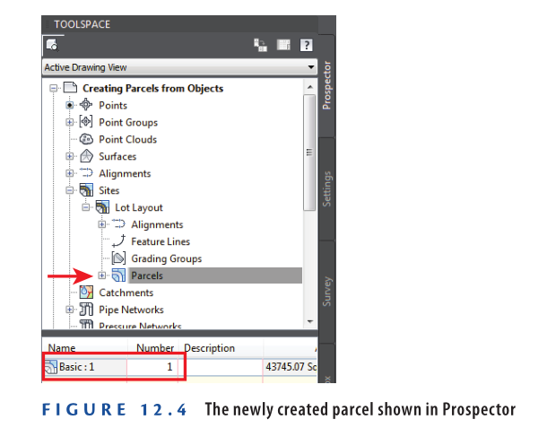
- Open Prospector, expand Sites ➢ Lot Layout, right-click Parcels, and select Refresh. A plus sign will appear next to Parcels, and a parcel named Basic: 1 should be listed in the Prospector item view (see Figure 12.4).
- If the item preview icon at the top left of Prospector is not activated, click it.
- Right-click Parcels and ensure that Show Preview is checked. If not, click Show Preview.
- Expand Parcels, then click Basic: 1 listed beneath it. The parcel shape preview will appear in the item view area.
- Click one of the red polylines in the drawing, right-click, and select Select Similar.
- On the Home tab in the ribbon, select Parcel ➢ Create Parcel From Objects.
- In the Create Parcels – From Objects dialog box, set Parcel Style to Property and click OK.
- Two new parcels will be created, as indicated by areas where the hatching is removed.
- In Prospector, right-click Parcels and select Refresh.
- Preview the parcels in the item view area as done earlier with the Basic: 1 parcel.
- Click one of the dashed right-of-way lines, right-click, and select Select Similar.
- Again, on the Home tab in the ribbon, select Parcel ➢ Create Parcel From Objects.
- Click OK to confirm the default settings in the Create Parcel – From Objects dialog box.
- Refresh and preview the parcels in Prospector again.
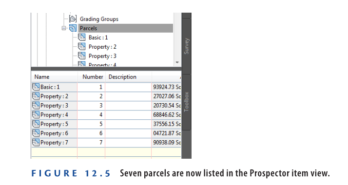
- Now, there should be seven parcels in total (See Figure 12.5).
- Save and close the drawing.
You can view the results of successfully completing this exercise by opening
Creating Parcels from Objects – Complete.dwg.
https://www.mediafire.com/file/waxo0teymw0gtur/Creating+Parcels+from+Objects+-+Complete.dwg/file
Watch Complete Video here for this Exercise:
Creating Parcels by Layout
Earlier in this chapter, you learned about the benefits of using basic AutoCAD drafting commands to generate parcel geometry. These commands are useful for drawing lines and curves based on general geometric principles. However, when creating parcels that need to fit a specific area, align perpendicularly to a road, or meet zoning depth requirements, specialized tools are required. Civil 3D 2025 includes built-in Parcel Layout Tools that streamline this process. When accessed from the ribbon, these tools appear on a dedicated toolbar similar to those used for alignments and profiles.
Parcel Terminology
Understanding key terms related to property boundaries is essential for parcel design:
- Parcel or Lot: A legally defined piece of land.
- Bearing: A horizontal direction in degrees relative to the north or south. For example, N 25° E means turning 25° east from the north. Bearings define parcel lines along with distances.
- Right-of-Way: A designated strip of land for transportation, often represented as a consistent width on both sides of a road centerline.
- Frontage: The length of a lot’s front boundary along a road. More frontage typically increases property value.
- Setback: The minimum distance required between a building and a property line, defined separately for front, rear, and side boundaries.
- Easement: A designated area on a property where another party has usage rights, such as for utility lines, without ownership.
- Zoning: A system for dividing land into zones with specific land-use regulations. For instance, one zone may require a minimum lot size of 5 acres (2 hectares), while another may allow 0.25 acres (0.10 hectares). Zoning regulations are typically managed by local authorities.
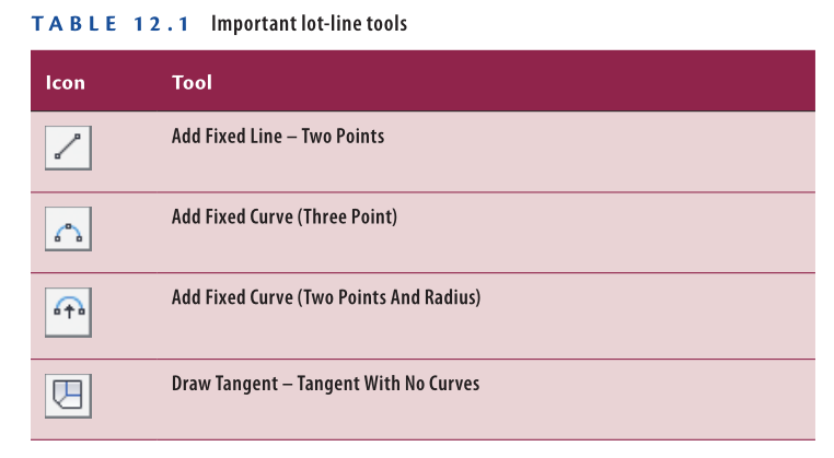
Using the Lot Line Tools
The first buttons on the Parcel Layout Tools toolbar enable basic parcel segment drafting, similar to AutoCAD’s line and curve tools, as shown in Table 12.1. These tools allow you to sketch parcels manually or trace existing geometry within the drawing.
Exercise 12.2: Create Parcels Using the Lot Line Tools
In this exercise, you will use the Parcel Creation Tools command to draw new parcel geometry. You will create a common area parcel near the entrance and a parcel representing land that will remain with the original owner.
Steps to Create Parcels:
- Open the drawing “Using the Lot Line Tools.dwg” which you can download from Video tutorial description below.
- Go to the Home tab in the ribbon, then click Parcel ➢ Parcel Creation Tools.
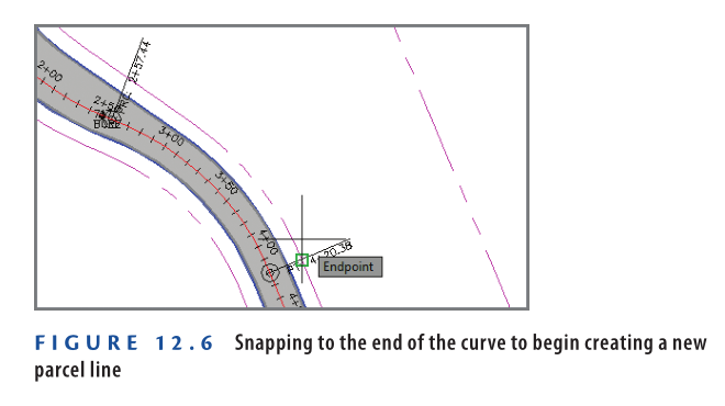
- On the Parcel Layout Tools toolbar, click Add Fixed Line – Two Points. Click OK to accept the defaults in the Create Parcels – Layout dialog box.
- Zoom into Jordan Court near station 4+00 (0+100). Hold the Shift key and right-click to open the Object Snap context menu.
- Click Endpoint, then select the end of the magenta curve at station 4+20.38 (0+128.13), as shown in Figure 12.6.
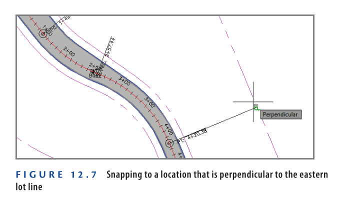
6: Hold down the Shift key and right-click.
7: Select Perpendicular from the Object Snap menu.
8: Click the magenta back-lot line, as shown in Figure 12.7. Press Esc twice to end the command.
- Click Parcel ➢ Parcel Creation Tools on the Home tab of the ribbon.
- Click Draw Tangent – Tangent With No Curves, then click OK to close the Create Parcels – Layout dialog box.
- Using the Endpoint object snap, trace the fence line surrounding the existing farm buildings. Start at the north end of the fence and move south and west.
- After selecting the last point on the fence, use the Perpendicular object snap to select the western boundary line, as shown in Figure 12.8.
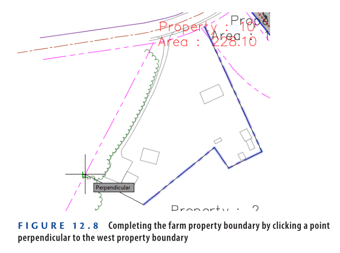
- Press Esc twice to exit the Parcel command.
- Save and close the drawing.
You can view the results of successfully completing this exercise by opening
Using the Lot Line Tools – Complete.dwg.
https://www.mediafire.com/file/0wu8oyvk0y0fmvu/Using+the+Lot+Line+Tools+-+Complete.dwg/file
Watch Complete Video here for this Exercise:
Using the Parcel Sizing Tools
The Parcel Sizing tools are among the most powerful features in Civil 3D. These tools allow you to create multiple lots within a defined area while ensuring each lot meets specific size parameters. They play a crucial role in residential land development projects.
Civil 3D provides three key tools for creating new lots based on size:
- Slide Line – Create: This tool generates one or more lots by adjusting a lot line along the frontage until all size and dimension criteria are met.
- Swing Line – Create: This tool creates lots by rotating a line around a fixed swing point, extending it until it intersects with a lot line across from the swing point. This results in lots radiating outward.
- Free Form – Create: This tool extends a line from a parcel segment at a specified angle (typically perpendicular) until it intersects another parcel segment, forming a new lot.
Exercise 12.3: Creating Parcels Using Parcel Sizing Tools
In this exercise, you’ll create multiple parcels using the Parcel Sizing tools.
- Open the drawing named Using the Parcel Sizing Tools.dwg which you can download from Video Tutorail Description below.
- On the Home tab, click Parcel ➢ Parcel Creation Tools.
- On the Parcel Layout Tools toolbar, expand the button containing the parcel sizing tools and select Slide Line – Create.
- Click OK to close the Create Parcels – Layout dialog box. When prompted, click the label Property: 25 at the southwest end of the project.
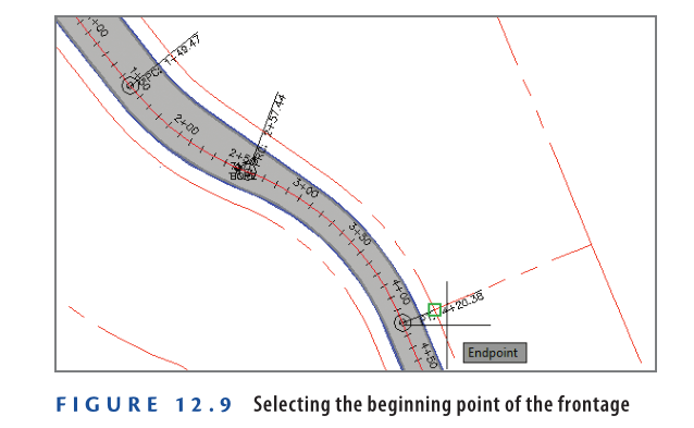
- When asked to select the first point on the frontage, click the western endpoint of the lot line previously created at station 4+20.38 (0+128.13), as shown in Figure 12.9.
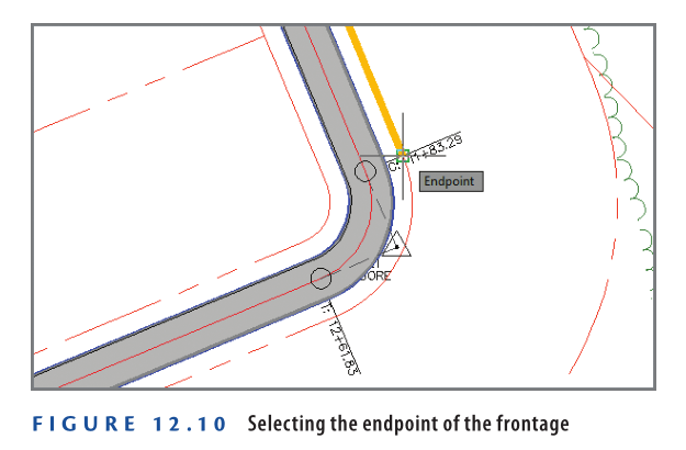
- Move your cursor in a southeastern direction along the frontage line. Note the orange “highlighter” that follows your cursor. Snap to the endpoint of the curve at station 11+83.29 (0+360.67), as shown in Figure 12.10.
- When prompted to specify the angle, type 90 in the command line and press Enter.
- A preview of the new parcel will appear near the frontage start point.
- Press Enter to confirm the current sizing parameters and create the parcel.
- Press Esc to exit the command while keeping the Parcel Layout Tools toolbar open.
- Click Swing Line – Create, then select the label Property: 2 near the southeastern corner of the project.
- When prompted for the start point of the frontage, snap to the northern endpoint of Property: 2, as shown in Figure 12.11.

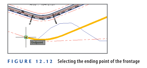
- When you’re prompted for the endpoint of the frontage, move your cursor in a westerly direction along the property line and snap to the western endpoint of the same parcel (see Figure 12.12).
- When prompted for the swing point, use the Endpoint object snap to select the property corner just south of the Property: 2 label.
- A preview of the parcel appears using the current Minimum Area setting of 10,890 sq. ft. (1,500 sq. m.).
- If the chevron at the right end of the Parcel Layout Tools toolbar is pointing downward, click it. If not, skip to the next step.
- In the expanded area beneath the Parcel Layout Tools toolbar, type 1 acre (0.4 hectare) for the Minimum Area value and press Enter.
- The preview updates to reflect the new area.
- Press Enter to create the parcel.
- This type of parcel is often used for environmental preservation areas, as required by agencies for mitigation.
- Press Esc to exit the current command. On the Parcel Layout Tools toolbar, click Free Form – Create and move the cursor along the property line east of the Property: 25 label.
- The preview line attaches to the parcel segment and extends outward until it intersects another segment.
- With the cursor on the west side of the line, snap to the midpoint of the parcel segment.
- When prompted for a direction, press Enter to specify perpendicular.
- Press Esc twice to clear the current command and close the Parcel Layout Tools toolbar.
- Save and close the drawing.
- To review the final result, open Using the Parcel Sizing Tools – Complete.dwg.
- To review the final result, open Using the Parcel Sizing Tools – Complete.dwg.
Watch Complete Video Tutorial here for this Exercise:
Using Parcel Sizing and Layout Parameters
The Parcel Layout Tools toolbar allows you to create and edit parcel geometry while ensuring compliance with zoning laws and developer requirements. The toolbar expands downward, revealing various parameters that define parcel dimensions.
Parcel Sizing Parameters
- Minimum Area: Defines the smallest allowable lot area, ensuring compliance with zoning laws.
- Minimum Frontage: Specifies the shortest allowable frontage along a road right-of-way.
- Use Minimum Frontage at Offset: Allows frontage measurement at the building setback line rather than the lot frontage, enabling smaller lots.
- Frontage Offset: Defines the building setback line.
- Minimum Width: Sets the minimum allowable width for a lot.
- Minimum Depth: Establishes the smallest depth a lot can have, measured perpendicular to the frontage midpoint.
- Use Maximum Depth: Prevents excessively deep lots for better subdivision efficiency.
- Maximum Depth: Defines the maximum allowable lot depth, measured perpendicular to the frontage midpoint.
Multiple Solution Preferences
- Use Shortest Frontage: If multiple solutions exist, the one with the shortest frontage is selected.
- Use Smallest Area: If multiple solutions exist, the smallest parcel area is chosen.
Parcel Layout Parameters
- Automatic Mode
- On: Creates multiple parcels at once based on specified parameters.
- Off: Creates parcels one at a time, requiring manual input for each.
- Remainder Distribution
- Create Parcel From Remainder: Forms a smaller parcel with the leftover area.
- Place Remainder in Last Parcel: Adds leftover area to the final parcel, making it oversized.
- Redistribute Remainder: Spreads the leftover area evenly across all parcels.
Create Multiple Parcels
In this exercise, you’ll create multiple parcels using the Slide Line Create command with Automatic Mode turned on.
- Open the drawing named Using Parcel Sizing Parameters.dwg which you can download from Video Tutorial Desciption below.
- On the Home tab of the ribbon, click Parcel ➢ Parcel Creation Tools. On the Parcel Layout Tools toolbar, change Automatic Mode to On.
- Click Slide Line – Create, then click OK to dismiss the Create Parcels – Layout dialog box. When prompted to select a parcel, click the label that reads Property: 30.
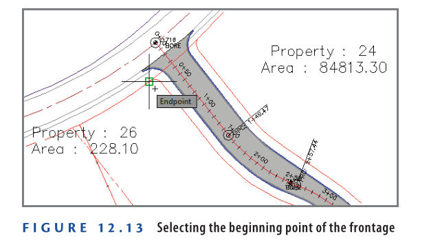
- When prompted for the start point of the frontage, snap to the endpoint of the right-of-way line at the entrance of Jordan Court, as shown in Figure 12.13.
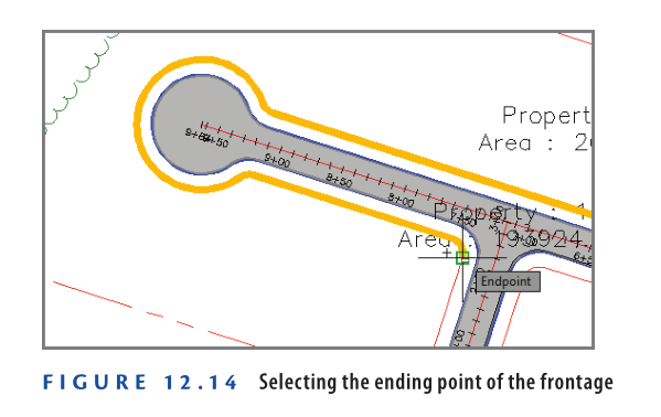
5: When prompted for the endpoint of the frontage, move your cursor along the west right-of-way line of Jordan Court, then along the north right-of-way line of Madison Lane. Move your cursor around the Madison Lane cul-de-sac and snap to the endpoint of the right-of-way line at the intersection of Madison Lane and Logan Court, as shown in Figure 12.14.
6: When prompted to specify an angle, press Enter.
7: On the Parcel Layout Tools toolbar, type 0.333 acres (or 0.135 hectares) for Minimum Area, and press Enter. The preview updates.
8: Change the following settings (noting how the preview updates after each):
- Minimum Frontage: 100 (35)
- Frontage Offset: 25 (8)
- Remainder Distribution: Redistribute Remainder
- Multiple Solution Preference: Use Smallest Area
9: Press Enter to create the parcels. Press Esc twice to end the command.
10: Save and close the drawing.
You can view the results of successfully completing this exercise by opening Using Parcel Sizing Parameters – Complete.dwg.
Watch Complete Video Tutorial here for this Exercise:
Editing Parcels
Civil 3D provides three fundamental tools to edit parcel geometry: grips, Edit Geometry commands, and Parcel Layout Tools.
Editing Parcels Using Grips
Graphically editing parcels is simpler compared to alignments or profiles. There are two types of grips:
- Square Grip: Allows unrestricted movement in any direction.
- Diamond-Shaped Grip: Appears on parcel lines created using the Parcel Layout Tools and allows sliding while maintaining the perpendicular angle.
Exercise 12.5: Edit Parcels with Grips
In this exercise, you’ll experiment with grip-editing parcel lines and observe their behavior.
- Open the drawing named Editing Parcels Using Grips.dwg which you can download from Video Tutorial description below.
- Zoom in to the parcel labeled Property: 28. Click the northern side of this parcel and observe the square grips that appear at both ends.
- Click the eastern square grip to select it. Move your cursor around and observe its behavior.
- Hold down the Shift key and right-click to open the object snap context menu. Select Nearest.
- Pick a point somewhere along the eastern property line of the lot.
- Press Esc to clear your selection. Click the line that forms the southern boundary of this parcel. A single diamond-shaped grip appears.
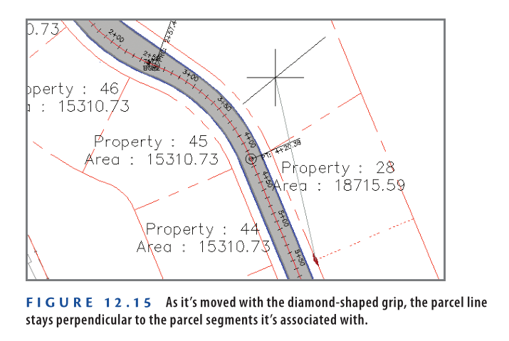
- Click the diamond-shaped grip and slide it along the attached parcel line. Move it north toward the curved areas, and observe how it stays perpendicular to the parcel segments it’s attached to (see Figure 12.15).
- Pick a new location for the line, and note the change to the parcel label.
- Save and close the drawing.
You can view the results of successfully completing this exercise by opening Editing Parcels Using Grips – Complete.dwg
Watch Complete Video here for this Exercise here:
Editing Parcels Using the Edit Geometry Commands
When modifying parcel lines and curves, you can use the Edit Geometry panel on the Parcel ribbon tab.
Edit Geometry Commands
- Insert PI: Adds an angle point to a parcel line segment.
- Delete PI: Removes an angle point from a parcel line segment.
- Break: Creates a gap in a parcel segment.
- Trim: Shortens a parcel segment using another entity as a cutting edge.
- Join: Joins two parcel segments together.
- Reverse Direction: Changes the direction of a parcel segment.
- Edit Curve: Modifies the radius of a parcel curve segment.
- Fillet: Replaces an angle point with a parcel curve segment that is tangent at both ends.
- Fit Curve: Replaces multiple parcel line segments with a single parcel curve segment.
- Stepped Offset: Similar to the AutoCAD offset command but prompts for an elevation and creates a polyline instead of a parcel segment.
Exercise 12.6: Edit Parcels with the Edit Geometry Commands
In this exercise, you’ll improve parcel geometry using the Edit Geometry commands on the ribbon.
- Open the drawing named Editing Parcels Using Edit Commands.dwg which you can download from Video tutorial description below.
- Zoom in to the area of the farm buildings and locate the small triangular parcel labeled Property: 26.
- Click the Property: 26 label. If the Edit Geometry panel isn’t visible on the ribbon, click Edit Geometry.
- Click Trim on the Edit Geometry panel of the contextual ribbon.
- When prompted for the cutting edge, select the parcel segment along the fence, then press Enter.
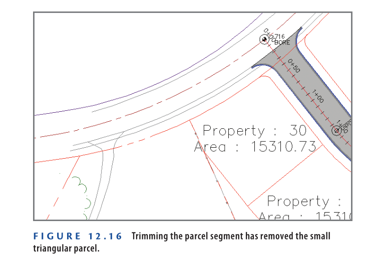
- When prompted for the objects to trim, click the west side of the small triangular parcel. The Property: 26 parcel disappears (see Figure 12.16), and the area of Property: 27 is updated.
- Press Esc to clear the current command. Pan southward and click the Property: 7 parcel label. Click Edit Curve on the ribbon.
- Click the curve just north of the Property: 7 label. In the Edit Feature Line Curve dialog box, enter 250 (85) for the radius value, and click OK. The parcel is updated.
- Press Esc twice to clear the current command and selection. Zoom in to the western end of the Property: 2 parcel.
- Click the north boundary of the Property: 2 parcel, and then click Delete PI on the ribbon. Click the triangle marker at the western end of the parcel line to delete the PI at that location.
- Press Esc twice to end the previous command. Click the parcel line again to reveal its grips. Click the westernmost grip, and snap it to the center of the red circle.
The parcel geometry has been improved (see Figure 12.17).

- Save and close the drawing.
You can view the results of successfully completing this exercise by opening Editing Parcels Using Edit Commands – Complete.dwg
Watch Complete Video Tutorial here for this Exercise:
Editing Parcels Using the Parcel Layout Tools
For advanced parcel editing, use the Parcel Layout Tools toolbar. This toolbar contains tools like Insert PI and Delete PI, also found in the Edit Geometry panel of the Parcel ribbon tab. It also includes editing versions of parcel-sizing commands.
The Slide Line – Edit and Swing Line – Edit commands function like their Create versions but modify existing parcel lines instead of creating new ones. Additionally, you can create a Parcel Union to merge multiple parcels into one entity. A separate command allows dissolving the union, restoring parcels to their original state.
Exercise 12.7: Edit Parcels with the Parcel Layout Tools
In this exercise, you will use tools from the Parcel Layout Tools toolbar to edit parcels.
- Open the drawing Editing Parcels Using the Layout Tools.dwg which you can download from Video Tutorial description.
- Click the Property: 28 parcel label and select Parcel Layout Tools from the ribbon.
- In the Parcel Layout Tools toolbar, set the minimum area to 0.5 acres (or 0.20 hectares) and press Enter.
- Expand Parcel Sizing Tools and click Slide Line – Edit. Click OK to close the Create Parcels – Layout dialog box.
- Select the southern boundary of Property: 28 when prompted for a lot line.
- Click anywhere inside Property: 28 when asked to select a parcel to adjust.
- For the frontage start point, snap to the northwest corner of Property: 28.
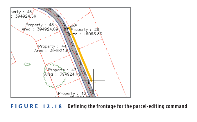
- Move the cursor southward along the right-of-way line and click near station 7+00 (0+210) as shown in Figure 12.18.
9: When prompted for the angle, press Enter to preview the resized parcel.
10: Press Enter again to confirm and complete the resizing.
11: Press Esc three times to clear the command and selection. Click the Property: 27 label and select Parcel Layout Tools from the ribbon.
12: On the Parcel Layout Tools toolbar, click Parcel Union.
13: When prompted for the destination parcel, click the Property: 3 label. The Property: 27 label disappears, and the area of Property: 3 updates.
14: Expand the Parcel Union icon and select Dissolve Parcel Union.
15: Click the Property: 3 label. The original parcels 3 and 27 reappear as separate parcels.
16: Save and close the drawing.
You can view the completed results by opening Editing Parcels Using the Layout Tools – Complete.dwg.
Watch Complete Video Tutorial here for this Exercise:
Now You Know
After completing this chapter, you can create parcels by converting existing objects or drawing custom parcel geometry. You can generate parcels that meet area, frontage, and other requirements, whether individually or in bulk. Additionally, you can edit parcels using grips, ribbon commands, and the Parcel Layout Tools toolbar.
You are now ready to create and modify parcels in a production environment.