Getting to Know the Civil 3D User Interface
Let’s simplify the experience of getting familiar with the Civil 3D environment by comparing it to learning to drive a car. When you first learned to drive, the focus was likely on the essentials: the steering wheel, the accelerator, and the brake pedal. Features like the air conditioning or radio, while useful, were introduced later. Similarly, we’ll focus on the most critical aspects of Civil 3D to help you get started.
The Civil 3D user interface has numerous components, but for now, we’ll concentrate on the ones that are essential for navigating the software efficiently. Figure 1.1 highlights the primary elements of the user interface, which will be the foundation of your learning experience.
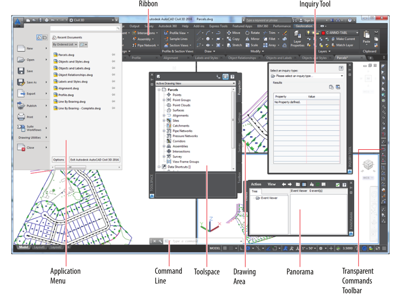
F I G U R E 1.1 Major components of civil 3d user interface
Key Components of the Civil 3D User Interface
- Application Menu
The hub for everyday file-management tasks like opening, saving, and printing your drawings. - Ribbon
The main area for accessing most Civil 3D commands. - Toolspace
Known as the “command center” of Civil 3D, it organizes all data and settings for your project. - Drawing Area
The workspace where your designs are created and visualized. - Command Line
A communication tool where you and Civil 3D exchange commands and feedback. - Panorama
A versatile window used for viewing and editing drawing properties and information. - Inquiry Tool
A feature packed with various tools to help you gather detailed information about your design. - Transparent Commands Toolbar
A specialized toolbar offering commands for drafting and geometric construction in a way tailored for civil engineers and surveyors.
Working with the Application Menu
The Application Menu (shown in Figure 1.2) is accessed by clicking on the square Civil 3D 2025 icon located at the top left of your screen. It contains essential commands for managing your drawing files, such as creating, opening, saving, and printing them.
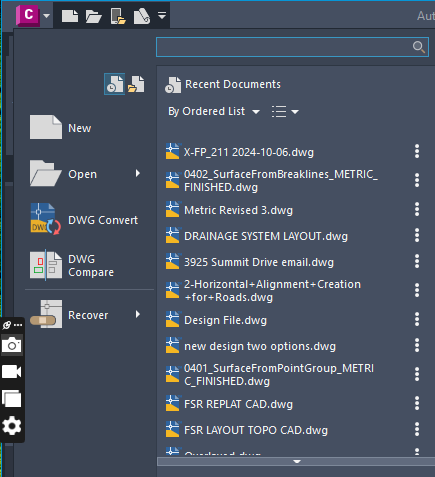
F I G U R E 1.2 Part of civil 3d Application menu
Exercise 1.1: Using the Application Menu to Open a File
In this exercise, you will learn how to use the application menu to open a file in AutoCAD Civil 3D.
- Launch Civil 3D: Start Civil 3D 2025 by double-clicking its icon on your desktop.
- Access the Application Menu: Click the application menu icon located in the top-left corner of the interface.
- Open a File: From the application menu, select Open.
- Locate and Open the File: Navigate to the file which you will get from the Youtube video Description and open the file named
User Interface.dwg. - Explore the Application Menu: Reopen the application menu and review the available commands. Observe that most options pertain to tasks such as creating, opening, saving, and printing drawing files.
- Keep the File Open: Leave the
User Interface.dwgfile open for use in the next exercise.
Note: Since this exercise does not modify the file, there is no need for a “completed” version of the drawing.
Watch the Video Tutorial
For a step-by-step video guide, watch here:
Working with the Ribbon
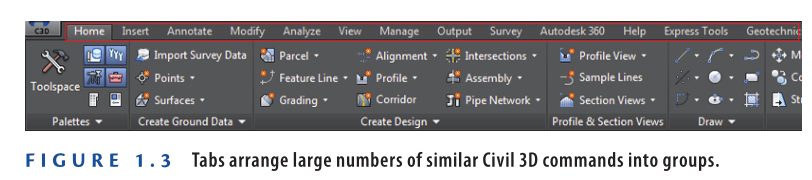
The ribbon is a key feature of the Civil 3D interface, located at the top of the screen. It serves as the primary hub for accessing most of the software’s commands. Commands on the ribbon are organized into logical groups using tabs and panels. These tabs include options such as Home, Insert, Annotate, and others, which streamline workflows and provide easy access to tools as shown in Figure 1.3.
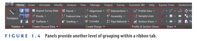
Each tab on the ribbon is divided into panels, which group related commands together. For example, the Home tab (as shown in Figure 1.4) includes panels such as Palettes, Create Ground Data, Create Design, Profile & Section Views, and Draw. These panels make it easier to find and use the tools you need for specific tasks.
Understanding Command Grouping in Civil 3D
Civil 3D organizes commands into tabs and panels, making it easier to locate tools without navigating through an overwhelming number of options. Once you identify the relevant tab and panel, you only need to choose from a few commands. With consistent use, you’ll naturally become more familiar with the layout and logic behind how commands are grouped. Instead of memorizing exact positions, you’ll develop an understanding of how Civil 3D categorizes and connects commands.
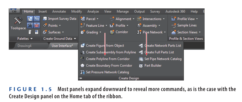
Many panels include additional, less frequently used commands that are hidden by default. You can identify expandable panels by a small downward-pointing white triangle next to their name. For example, as illustrated in Figure 1.5, the Create Design panel under the Home tab can be expanded to reveal more options. Remember to check these hidden panels when searching for specific commands.
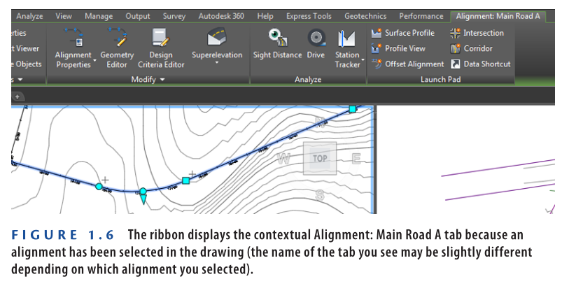
One of the most powerful aspects of the ribbon is its ability to adapt based on what you select in the drawing area. For instance, if you select a Civil 3D alignment, the ribbon dynamically updates to display alignment-specific commands on a dedicated tab. This behavior applies to other objects as well, such as surfaces, parcels, and more.
These specialized tabs are known as contextual ribbon tabs. They are incredibly helpful for beginners, guiding you to the relevant tools for the selected object. Even for experienced users, these tabs are a significant time-saver, streamlining workflows and reducing the need to search for commands.
An Efficient Way to Locate Commands
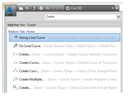
If you’re unsure where to start looking for a command, the search tool in the application menu can be a lifesaver. Simply click the application menu and type a keyword into the search bar. The tool will provide a list of commands that match your keyword.
From there, you can either launch a command directly by clicking it or learn its location by reviewing the details displayed to the right of the command. This feature is especially useful when navigating Civil 3D’s extensive interface.
Exercise 1.2: Using the Ribbon to Launch Commands
In this exercise, you will explore the ribbon’s tabs and panels to become more familiar with its functionality.
- Launch Civil 3D: Open Civil 3D 2025 and load the file named
User Interface.dwg. which you can download from Youtube video description below the exercise. - Access the Home Tab: Click the Home tab on the ribbon to bring it to the forefront (it might already be active).
- Expand a Panel: Locate the Create Design panel on the Home tab and click the small downward-pointing white triangle at its bottom. Notice how it expands to reveal additional commands (refer to Figure 1.5).
- Explore the Insert Tab: Click the Insert tab on the ribbon. Here, you’ll find options like Insert, Import, and Attach, which are used for bringing external data into the drawing.
- Browse Other Tabs: Click through the other ribbon tabs and observe the commands. Try to relate the commands you see to the tab titles, such as Annotate, View, or Analyze.
- Zoom In on the Drawing: Place your cursor in the left viewport and use the mouse wheel to zoom in. Continue zooming until you can clearly see the road centerlines labeled with stationing numbers (these represent Civil 3D alignments).
- Observe Contextual Tabs: Click one of the road centerlines. Notice that a contextual tab appears on the ribbon, providing commands specific to alignments (refer to Figure 1.6).
- Keep the Drawing Open: Leave this drawing open for the next exercise.
Note: Since no changes are made to the drawing during this exercise, a “completed” version of the file is not required.
Watch the Video Tutorial:
For a step-by-step video guide, watch here:
Working with the Toolspace
The Toolspace in Civil 3D serves as the “command center” for managing all Civil 3D data and settings. It organizes various tools and information in a structured layout. The Toolspace includes several key tabs that represent different functions within the software. These tabs are:
- Prospector
- Settings
- Survey
- Toolbox
These tabs provide easy access to Civil 3D’s data and settings, making it a vital part of the user interface.
Prospector Tab
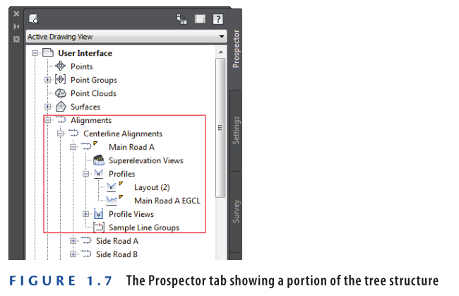
The Prospector tab is one of the most essential components of the Civil 3D user interface. As you work on your design, the Prospector organizes various parts of your project into a tree structure (as shown in Figure 1.7).
Why use a tree structure instead of a simple list of items? Later in this Course, you’ll explore how Civil 3D establishes relationships between different design elements. In many ways, the tree structure represents these relationships in a hierarchical manner. Another practical reason for using a tree structure is its ability to efficiently display a long list of items in a compact space. The branches of the tree can be collapsed to create room for expanding other sections.
Another way to think of the Prospector tab is as a tool that organizes your design by category rather than by spatial arrangement. In your drawing area, you might see elements like road centerlines crossing through parcels, which in turn cross through contours and survey points. While these objects are correctly placed spatially, the organization may feel chaotic. The Prospector tab helps by sorting these elements into categories: all points in one location, all parcels in another, and so on.
In addition to organizing the design, Prospector also knows the exact location of these objects within the drawing. By right-clicking on an object in Prospector, you can use commands such as Select or Zoom To to quickly locate that object in the drawing area.
Exercise 1.3: Explore the Model with the Prospector Tab
In this exercise, you will use the Prospector tab in the Toolspace to explore your model and understand how it organizes design elements.
- Launch Civil 3D: Open Civil 3D 2025 and load the file named
User Interface.dwg. which you can download from Youtube video description under the exercise. - Open the Toolspace: If the Toolspace is not already visible, click Toolspace on the Home tab of the ribbon.
- Activate the Prospector Tab: Click the Prospector tab within the Toolspace to bring it to the forefront.
- Explore the Tree Structure: Click the plus signs next to items to expand the different branches of the Prospector tree structure.
- Navigate to Alignments: Expand the following hierarchy: Alignments ➢ Centerline Alignments ➢ Main Road A ➢ Profiles. This organization demonstrates the relationship between the alignment and its associated profiles.
- Zoom to an Alignment: Click within the left viewport to activate it. Then, right-click on Side Road B in the Prospector tab and select Zoom To. Notice how Prospector automatically zooms to the location of Side Road B, even if you don’t know its exact position.
- Keep the Drawing Open: Leave this drawing open for the next exercise.
Note: No changes are made to the drawing during this exercise, so a “completed” version of the file is not required.
Watch Video Tutorial here:
For a step-by-step video guide, watch here:
It’s important to note that Prospector is not only used to view your design but also allows you to modify its appearance.
In Prospector, you can create new components for your design, edit existing elements, and perform other tasks. These functions are accessed through contextual menus, such as the one used in step 6 of Exercise 1.3. A helpful tip when working with Prospector is: “When in doubt, right-click it.” Right-clicking on any item often reveals a list of available actions, making it easier to interact with your design.
Settings Tab
Civil 3D provides a vast array of settings that govern almost every aspect of how the software functions. One of the key strengths of Civil 3D is its high level of customization, allowing you to adjust settings to fit specific design needs, company standards, or any other unique requirements. The Settings tab is where you manage these configurations.
However, as a beginner, you may not spend much time here initially. This area is typically more relevant for CAD managers or experienced Civil 3D users who are responsible for configuring the software’s settings to align with project or organizational needs.
Exercise 1.4: Explore the Drawing Settings with the Settings Tab
In this exercise, you will use the Settings tab in the Toolspace to explore various drawing settings.
- Launch Civil 3D: Open Civil 3D 2025 and load the file named
User Interface.dwg. which you can download from Youtube video description. - Open the Toolspace: If the Toolspace is not already open, click Toolspace on the Home tab of the ribbon.
- Access the Settings Tab: Click the Settings tab in the Toolspace.
- Explore Surface Styles: Expand Surface ➢ Surface Styles and review the list of styles available. These styles control the appearance of models that represent the ground surface.
- Explore Label Styles: Expand Surface ➢ Label Styles ➢ Contour and review the available styles. These styles control the labeling of contours on surface models.
- Keep the Drawing Open: Leave this drawing open for the next exercise.
Note: No changes are made to the drawing during this exercise, so a “completed” version of the file is not required.
Watch the Video Tutorial for this Exercise:
For a step-by-step video guide, watch here:
Survey Tab
The Survey tab is tailored for working with survey data. It can be thought of as a “Prospector for surveyors” because it functions similarly to the Prospector tab. The Survey tab displays survey data in a tree structure, making it easy to navigate, and it also provides the ability to launch commands through contextual menus.
Toolbox Tab
The Toolbox tab is another feature that expands Civil 3D’s functionality. It serves as a place to load additional add-ons, whether they are custom programming tools created by your company or modules provided by Autodesk. This is where you can integrate and run enhancements that add extra features to Civil 3D.
Using the Drawing Area
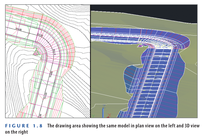
The Drawing Area is where you can see and interact with the design model you’re working on. Typically, the design is viewed from above in plan view, but Civil 3D allows you to view it from any perspective. Since Civil 3D is geared towards 3D modeling, you may also want to view your model in a 3D view. Figure 1.8 illustrates a model displayed in both plan and 3D views.
Using the Command Line
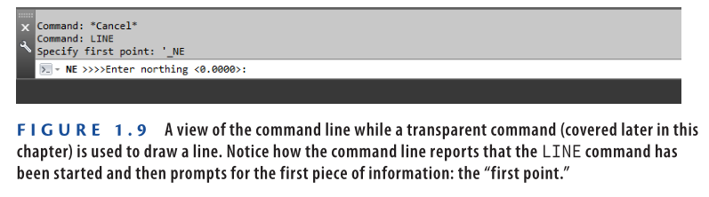
Think of the Command Line ( see figure 1.9) as a “chat window” where you interact with Civil 3D. It provides a real-time dialogue between you and the software, reporting everything you do and displaying responses from Civil 3D. These responses might include requests for more information, results, or notifications about issues.
It’s a good habit to always keep an eye on the command line, as it often provides guidance on what to do next. While you can launch commands directly from the command line, you’ll typically find the visual interface offered by the ribbon and other tools more intuitive and user-friendly.
Using Panorama
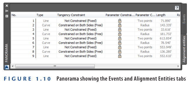
Panorama is a versatile window used to display and modify various types of information within Civil 3D. It operates by showing a tab for the specific information requested by the user or the program. For instance, the Events tab (also known as the Event Viewer) appears when Civil 3D needs to provide information about the drawing.
Another example is when you edit the geometric details of an alignment—the Alignment Entities tab will appear. As shown in Figure 1.10, Panorama displays the information relevant to one task while also providing access to tabs for other tasks. This design allows you to multitask efficiently within a single window.
Exercise 1.5: Explore Panorama
In this exercise, you will open the Event Viewer and Volumes Dashboard to become familiar with Panorama.
- Launch Civil 3D 2025, and open the file named User Interface.dwg which you can download from Youtube video description under the exercise.
- On the Home tab of the ribbon, expand the Palettes panel and click the icon for Event Viewer.
- Experiment with resizing, auto-hiding, and docking the Panorama window. It behaves similarly to other dockable windows in Civil 3D.
- Press Esc to clear any selections in the drawing. Click one of the contour lines in the drawing to display the Tin Surface: Existing Ground ribbon tab, then click Volumes Dashboard on the Analyze panel.
- Close Panorama, and close the drawing without saving.
Because no changes are made to this drawing file as a result of the exercise steps, no User Interface – Complete file is necessary.
Watch the Complete video tutorial here for this exercise:
Using the Transparent Commands Toolbar
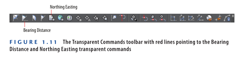
As you may already know, civil engineers and surveyors draw things differently than other fields, using concepts such as bearings, curve deltas, northings, and eastings to define geometry. The Transparent Commands toolbar enables Civil 3D users to draw based on these specialized geometric concepts unique to civil engineering and surveying.
For example, when drawing a line, you can use the Northing Easting transparent command to specify the first point and the Bearing Distance transparent command to define the endpoint (see figure 1.11)
Exercise 1.6: Use Transparent Commands to Draw Like a Civil Engineer
In this exercise, you will use one of the Transparent Commands to draw a line by bearing and distance.
- Launch Civil 3D 2025, and open the file named Line By Bearing.dwg. which you can download from Youtube video desciption.
- Click the Type a command prompt on the command line. Type LINE, and press Enter.
- When prompted to specify the first point, click a point near the center of the screen.
- When prompted to specify the next point, click Bearing Distance on the Transparent Commands toolbar. Refer to Figure 1.11 for the location of this command.
- When prompted for a quadrant, either type 1 and press Enter, or click in the upper-right quadrant created by the crosshairs on the screen.
- When prompted for the bearing, type 45 and press Enter.
- When prompted for the distance, type 500 (or 150 for meters) and press Enter. Press Esc twice to exit the command. You have just drawn a line that is 500 feet (or 150 meters) long at a bearing of N 45° E.
- Save and close the drawing.
To view the results of completing the exercise successfully, you can open Line By Bearing – Complete.dwg. here:
https://www.mediafire.com/file/7o9bfpb0dz0lkpc/Line+By+Bearing+-+Complete.dwg/file
Watch Complete video tutorial here for this exercise:
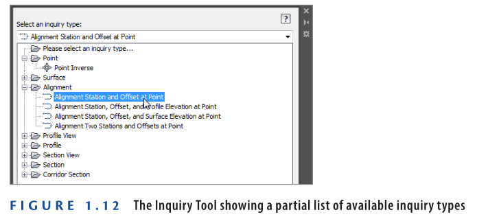
Using the Inquiry Tool
Most of the time, you’ll be the one providing the information for a drawing. Sometimes, however, you need your drawing to tell you something. That’s where the Inquiry Tool comes in. The Inquiry Tool is a separate window whose sole purpose is to give you information about things in the drawing. There is a long list of drawing items from which to choose, and beneath each item is a list of things that you can ask about (see Figure 1.12).
Using Specialized Line and Curve Commands
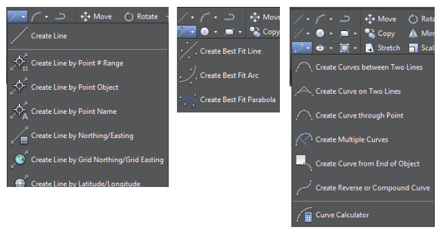
Another Civil 3D feature that enables you to draw like a surveyor or civil engineer is a set of specialized line and curve commands. These commands are mixed in with the basic AutoCAD line and curve commands on the Draw panel of the ribbon. You can find specialized line commands by expanding the Line icon to reveal commands like Create Line By Bearing, Create Line By Point # Range, and so on.
There is also a Curves icon that expands to reveal commands like Create Curve Through Point and Create Multiple Curves. Finally, the Best Fit icon expands to include commands for best-fit lines and curves. The following image shows the expanded form of the Line, Curve, and Best Fit icons.
Exercise 1.7: Use the Inquiry Tool to Answer Questions
In this exercise, you will use the Inquiry Tool to analyze the line that was drawn in the previous exercise.
- Launch Civil 3D 2025, and open the file named Inquiry.dwg. which you can download from Youtube video description at the end of this exercise find the link.
- On the Analyze tab of the ribbon, click Inquiry Tool.
- Under Select An Inquiry Type, select Point → Point Inverse.
- When prompted to specify the first point, hold down the Shift key, right-click, and select Endpoint on the contextual menu that appears.
- Click the southwestern endpoint of the line you drew earlier.
- Use the Shift+right-click combination again to select Endpoint, and then click the opposite end of the line for the second point.
- Scroll down to the Direction and Horizontal Distance values in the Inquiry Tool window. Note that they show the same bearing and distance that you entered earlier.
Because nothing has changed in this drawing file, no Inquiry – Complete file is available.
Watch Complete video tutorial here for this exercise:
Now You Know
Now that you have completed this chapter, you are more comfortable in the Civil 3D user interface and can begin navigating it to get where you need to go. You understand how to use the application menu to access files and perform other general tasks. You can use the ribbon to access Civil 3D commands and the Toolspace to explore the model contents and the drawing settings. You understand where Panorama fits into the overall user interface makeup. You can use transparent commands to perform basic drafting using terms and geometric concepts that are unique to those working in the civil engineering and surveying fields. Finally, you can use the Inquiry Tool to answer questions about your design.
Now that you have a feel for the Civil 3D user interface, you are ready to move on in your learning experience. Next, you will study the nature of the Civil 3D environment in all its dynamic 3D glory, and you will begin to build and create a design, learning new tools and concepts as you go.
For All videos of Chapter-1: