Chapter 1: Introduction to Surveying
Definition for Surveying
- The science, art, and technology involved in determining the relative positions of points on, above, or below the Earth’s surface.
- A field that encompasses various methods for measuring and gathering data about the physical environment, processing this information, and delivering diverse outputs to a broad range of users.
What do we do in SURVEYING?
Earth Measurements
- Distances: Includes horizontal, slope, and vertical measurements.
- Angles: Covers horizontal, vertical, and zenith angles.
- Relative Positioning: Determining the location of points on, above, or below the Earth’s surface.
- Position Calculation: Achieved through mathematical processing of field measurements.
- Final Output: Provides positional data in the form of:
- Maps – Available in digital and paper formats.
- Coordinates – Precise numerical representation of locations.
- Features – Physical and environmental attributes of surveyed areas.
Why Surveying is Important
Role of Surveying in Civil Engineering
- The planning and design of buildings, parks, roads, bridges, tunnels, sewers, and other infrastructure rely on data gathered through surveying.
- During construction, projects of any scale are built based on reference points and alignments established by surveying.
- Therefore, surveying is a fundamental requirement for all civil engineering projects.

Types of Surveying
Types of Surveying
- Land, Boundary, and Cadastral Surveying
Focuses on marking and mapping property boundaries, as well as defining land ownership rights. - Construction and Route Surveying
Involves surveying tasks for planning, designing, executing, and monitoring construction projects such as roads, bridges, buildings, and infrastructure networks. - Quantity Surveying
Includes fieldwork and calculations for determining project quantities, such as earthworks (cut and fill) and construction materials. - Plane Surveying (Covered in This Course)
Suitable for projects over small areas where the Earth’s curvature is negligible and can be ignored. - Geodetic Surveying
A branch of geodesy that deals with large-scale projects where Earth’s curvature must be considered. - Topographic Surveying
Focuses on identifying locations and elevations of natural and man-made features for map creation.
Course Organization and Contents
Fundamentals of Surveying
Basics of Surveying
- Arithmetic and Measurements: Understanding percentages, ratios, and proportions in surveying calculations.
- Geometry: Types of angles, properties of polygons, triangles, and circles.
- Angles in Surveying: Concepts of bearings and azimuths in line direction measurements.
- Theory of Errors: Definitions, types, sources of errors, and precision measurement techniques.
Measurements and Field Practice
- Distance Measurement: Measuring slope, horizontal, and vertical distances using tapes, electronic distance measurement (EDM) instruments, and leveling methods while accounting for errors.
- Direction and Angle Measurement: Utilizing theodolites and total stations for precise angle and direction measurements.
Applications
- Topographic Surveying and Mapping: Understanding contour lines, their characteristics, contour map construction, and interpretation.
- Traversing: Applications of open and closed traverses, latitude and departure calculations, error detection, and correction techniques.
- Areas and Volumes: Determining traverse areas, profiles, and cross-sections using various methods, and calculating earthwork volumes using grids or contour maps.
Chapter 2: Basic Surveying Math
Subjects
Essential Mathematical Concepts in Surveying
- Percentages – Fundamental calculations for scaling and comparisons in surveying.
- Pythagorean Theorem – Essential for distance and height calculations in right-angled triangles.
- Ratio and Proportion – Used for scaling and proportional measurements.
- Types of Angles – Understanding different angle classifications and their applications in surveying.
- Polygons – Properties and applications of multi-sided shapes in surveying calculations.
- Triangles – Classification and properties of triangles relevant to land measurements.
- Rectangles and Squares – Basic geometric shapes used in area and boundary calculations.
- Trapezoids – Properties and applications in land area computation.
- Circles and Arc Length – Calculating the length of arcs and circular measurements.
- Perimeter – Determining the total boundary length of different geometric shapes.
- Solution of Oblique Triangles – Applying trigonometric principles to solve non-right-angled triangles.
Percentages
Understanding Percentages
The term “percent” originates from a Latin word meaning “by the hundred.” The “%” symbol represents percent. A fraction with 100 as the denominator expresses a percentage.
Examples:
- Converting Fractions or Decimals to Percent:
- 0.005=51000=51000×100%=0.5%0.005 = \frac{5}{1000} = \frac{5}{1000} \times 100\% = 0.5\%0.005=10005=10005×100%=0.5%
- Converting Percent to Fraction or Decimal:
- 0.7%=0.7100=71000=0.0070.7\% = \frac{0.7}{100} = \frac{7}{1000} = 0.0070.7%=1000.7=10007=0.007
- 150%=150100=1.50150\% = \frac{150}{100} = 1.50150%=100150=1.50
More Examples:
- Finding a percentage of a number:
- 1%1\%1% of 7823 → 7823×1100=78.237823 \times \frac{1}{100} = 78.237823×1001=78.23
- 68%68\%68% of 300 → 300×68100=204300 \times \frac{68}{100} = 204300×10068=204
- Finding what percentage one number is of another:
- 15 is what percent of 750?
15750×100%=2%\frac{15}{750} \times 100\% = 2\%75015×100%=2%
- 15 is what percent of 750?
- Finding the whole when a percentage of it is known:
- If 30 is 75% of a number Y, find Y:
30=75100×Y30 = \frac{75}{100} \times Y30=10075×Y
Y=40Y = 40Y=40
- If 30 is 75% of a number Y, find Y:
Ratio and Proportion
Understanding Ratios and Proportions
Ratios:
A ratio is a comparison between two quantities. It can be written in different formats, such as:
- 2 to 5
- 2 : 5
- 2 ÷ 5
- 2 / 5
In surveying, ratios are often expressed in the form of:
- 1 to x
- 1 : x
- 1 ÷ x
- 1/x
Proportions:
A proportion represents the equality between two ratios. For example, the proportion:
- 2:5 = 4:10
- 2 ÷ 5 = 4 ÷ 10
- 2/5 = 4/10
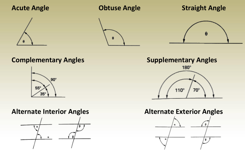
Geometry: Angles
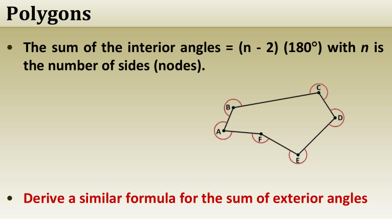
Polygons
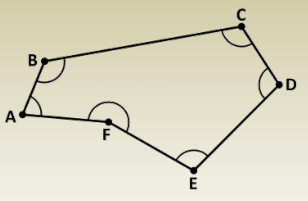
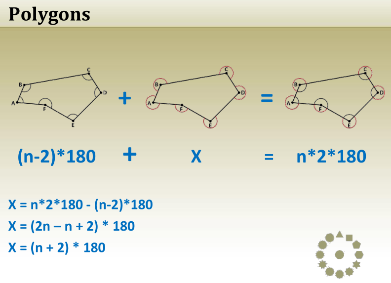
Polygons and Interior Angles
- A polygon is a closed shape formed by straight lines lying in the same plane.
- The sum of the interior angles of a polygon is determined by the formula:
Sum of Interior Angles=(n−2)×180∘\text{Sum of Interior Angles} = (n – 2) \times 180^\circSum of Interior Angles=(n−2)×180∘
where n represents the number of sides.
Examples:
- A triangle (3 sides) → (3−2)×180∘=180∘(3 – 2) \times 180^\circ = 180^\circ(3−2)×180∘=180∘
- A rectangle (4 sides) → (4−2)×180∘=360∘(4 – 2) \times 180^\circ = 360^\circ(4−2)×180∘=360∘
- A pentagon (5 sides) → (5−2)×180∘=540∘(5 – 2) \times 180^\circ = 540^\circ(5−2)×180∘=540∘
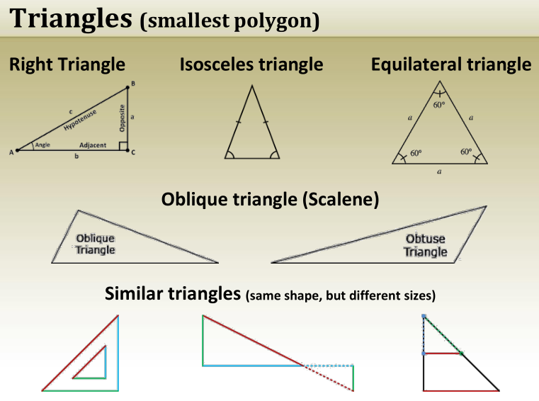
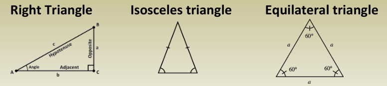
Triangles (smallest polygon)
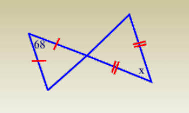
Exercise:
Find the measure of angle x
T/F: If a triangle is equilateral, then it is isosceles.
T/F: If a triangle is isosceles, then it is also equilateral.
Triangles (smallest polygon)
Exercise:
Which of the following triangles are always similar?
Exercise Solution:
Given:
- A triangle with sides 5, 6, and 10.
- A similar triangle where the shortest side is 15.
Since the triangles are similar, their sides are proportional. The ratio of similarity is:155=3\frac{15}{5} = 3515=3
Thus, multiplying the other sides by 3:6×3=18,10×3=306 \times 3 = 18, \quad 10 \times 3 = 306×3=18,10×3=30
Answer: The longest side of the similar triangle is 30.
True/False Question:
Statement: Similar triangles are exactly the same shape and size.
Answer: False – Similar triangles have the same shape but can have different sizes.
Solution to Right Triangles
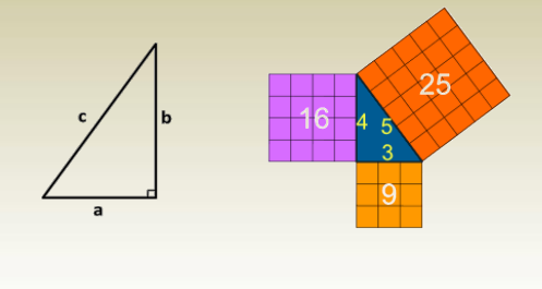
The Pythagorean Theorem
In a right-angled triangle, the square of the hypotenuse is equal to the sum of the squares of the other two sides.c2=a2+b2c^2 = a^2 + b^2c2=a2+b2
where:
- c = Hypotenuse (longest side)
- a, b = Other two sides
Rearranging for Side Calculation:
- If c is known: a2=c2−b2a^2 = c^2 – b^2a2=c2−b2 b2=c2−a2b^2 = c^2 – a^2b2=c2−a2
This theorem is widely used in surveying, engineering, and construction for distance and angle calculations.
Solution of Oblique Triangles
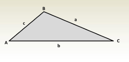
Solving Oblique Triangles )
- A triangle consists of six elements: three angles and three sides.
- An oblique triangle (a triangle without a right angle) can be solved if three of its elements are known, provided that at least one of them is a side.
- These triangles are solved using the Law of Sines or the Law of Cosines.
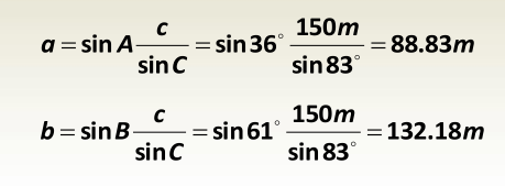
Law of Sines:
asinA=bsinB=csinC\frac{a}{\sin A} = \frac{b}{\sin B} = \frac{c}{\sin C}sinAa=sinBb=sinCc
Law of Cosines:
c2=a2+b2−2abcosCc^2 = a^2 + b^2 – 2ab \cos Cc2=a2+b2−2abcosC b2=a2+c2−2accosBb^2 = a^2 + c^2 – 2ac \cos Bb2=a2+c2−2accosB a2=b2+c2−2bccosAa^2 = b^2 + c^2 – 2bc \cos Aa2=b2+c2−2bccosA
Solution of Oblique Triangles
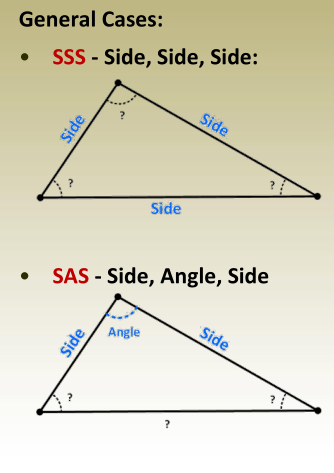
Law of Cosines → Find any angle
Law of cosines or law of sines → Find
another angle
Law of cosines or law of sines or
summation of angles → Find the last
angle
Law of Cosines → Find the third side
Law of cosines or law of sines → Find
one unknown angle
Law of cosines or law of sines or
summation of angles → Find the last
angle
Solution of Oblique Triangles
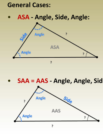
Summation of angles → Find the third
angle
Law of sines → Find another side
Law of cosines or law of sines → Find
the last side.
Summation of angles → Find the third
angle
Law of sines → Find the 2 nd side
Law of cosines or law of sines → Find
the last side
Solution to Oblique Triangles
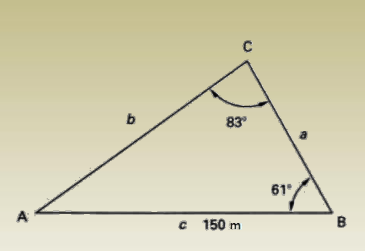
Example
Solve for the unknowns are A, a, b.
This is a SAA or AAS case
Start with summation of angles
A = 180 -(83 + 61 ) = 36
Continue with the law of sines
Rectangles and Squares
A rectangle is a four-sided polygon whose angles are right angles. A
square is a rectangle whose sides are equal
Trapezoid (Trapezium)
A trapezoid is a four-sided polygon that has two parallel sides and two
nonparallel sides.
Parallelograms and Rhombi
A parallelogram is a four-sided polygon with pairs of parallel sides. A
rhombus (plural – rhombi) is its special case with all sides equal
(equilateral).
Circles
A circle is a closed plane curve, all points on which are equidistant from
a point within called the center.
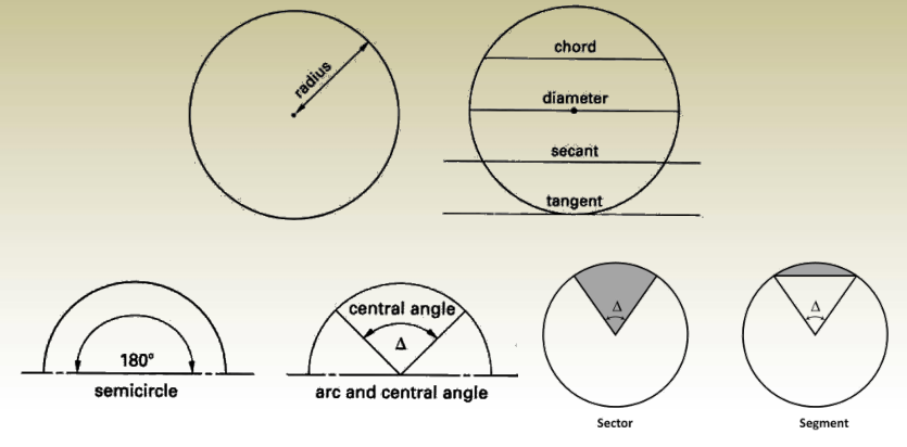
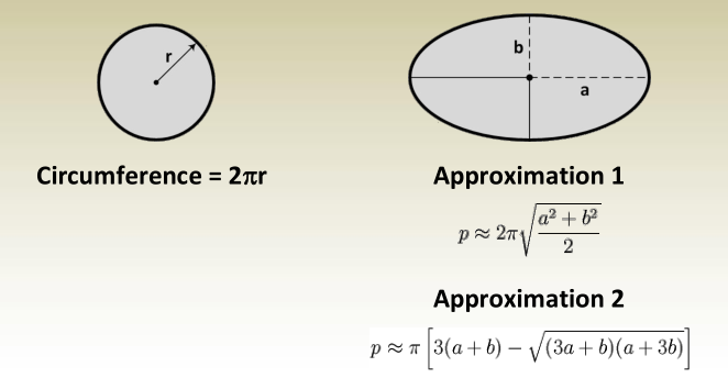
Circumference
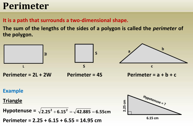
It is the perimeter of a circle or an ellipse.
The sum of the lengths of the sides of a polygon is called the perimeter
of the polygon.
Chapter 3: Basics of Surveying
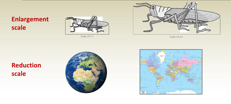
Drawing Scale
-A map cannot be the same size as the area it represents.
-A scaled drawing of a building maintains the same shape as the actual structure it represents but differs in size.
Common conventional scales
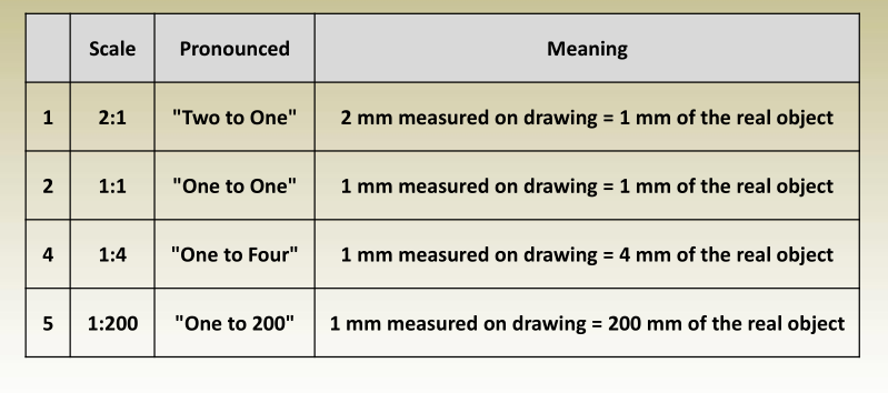
Types of Map Scale
- Verbal Scale
Describes the relationship between map distance and ground distance using words.
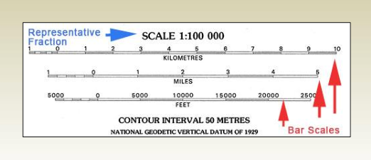
Example: “One centimeter represents one kilometer” means 1 cm on the map equals 1 km in reality. - Representative Fraction Scale (Ratio Scale)
Expresses the ratio of map distance to ground distance in numerical form, such as 1:X or 1/X. - Graphic (Bar) Scale
A visual scale represented as a line marked with distances, allowing users to measure directly using a ruler.
Representative Fraction
RF is the ratio of map distance to ground distance.
Properties
- Uses the ( : ) or ( / ) ratio formats;
- has 1 as the map distance, and
- has no units
- In other words RF is the map distance divided by the ground
distance in the same units. - Examples
- 1 : 100
- 1 / 150
- If the ratio has units, it must be converted and removed
Example 1
Write the scale 1 cm to 1 m in RF format.
1 cm to 1 m = 1 cm : 1 m
= 1 cm : 100 cm
= 1 : 100
Example 2
Simplify the scale 5 cm : 2 km to RF format
5 cm : 2 km = 5 cm : 2000 m
= 5 cm : 200,000 cm
= 5 : 200,000
= 1 : 40,000
To determine the scale of the drawing do the following:
1 Drawing distance
—– = —————————
X Ground distance
a. Pick an actual distance from the drawing. Take the 200 m distance
(why?)
b. Use a ruler to measure the corresponding drawing distance in
millimeters, it was found = 50 mm.
c. 1: X = drawing distance : ground distance ( a proportion )
drawing distance : ground distance
50 mm : 200 m
50 mm : 200000 mm
50 : 200000
1 : 4000
d. Scale is 1 : 4000
Convert map distances to ground distances
If the map scale is 1 : X
1 Map distance
—– = ————————-
X Ground distance
Ground distance = Map distance * X
Example
A particular map shows a scale of 1 : 5000. What is the
ground distance if the map distance is 8 cm?
Ground distance = 8 cm * 5000 = 40000 cm = 400 m
Convert ground distances to map distances
If the scale is 1 : x
1 Map distance
—– = ————————-
X Ground distance
Map distance = Ground distance / X
Example
A particular map shows a scale of 1 cm : 5 km, What is the
map distance (in cm) if the ground distance is 14 km?
Unify the scale: 1 cm : 5 km means the scale is 1 cm : 500,000 cm or
1:500,000
Map distance = 14 km * 100,000 / 500,000 = 2.8 cm
Graphic (Bar) Scale
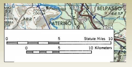
A line marked with distances on the ground, allowing the map user to measure and determine the scale using a ruler.
Converting Between Scale Types
-Verbal to RF
The key here is to write the verbal scale as a fraction,
then convert both sides to the same units, and make the
left side = 1.
-Verbal to Graphic
-RF to Graphic
-RF to Verbal
-Graphic to RF
Finding area measurement
Finding Area Measurement from a Map and Scale
- Area must be expressed in square units, such as cm², km², etc.
- Squared conversion factors must be used when calculating the area from map measurements.
Example:
A rectangular property measures 3 cm × 4 cm on a map with a scale of 1:24,000.
The area in ground units is:3×24,000×4×24,000=12×24,00023 \times 24,000 \times 4 \times 24,000 = 12 \times 24,000^23×24,000×4×24,000=12×24,0002 12×576,000,000=6,912,000,000 cm2=691,200 m212 \times 576,000,000 = 6,912,000,000 \text{ cm}^2 = 691,200 \text{ m}^212×576,000,000=6,912,000,000 cm2=691,200 m2
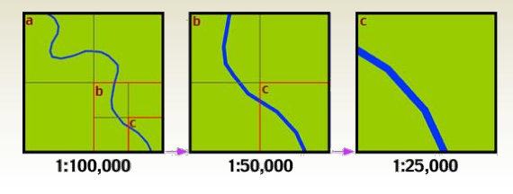
Large Scale vs. Small Scale Maps
- Small-scale maps cover large areas with less detail.
- Large-scale maps cover smaller areas with more detail.
For example, in a set of maps:
- A 1:100,000 map has the smallest scale.
- A 1:25,000 map has the largest scale.
Angle Measurement Systems
The following angle unit systems will be discussed in this
chapter.
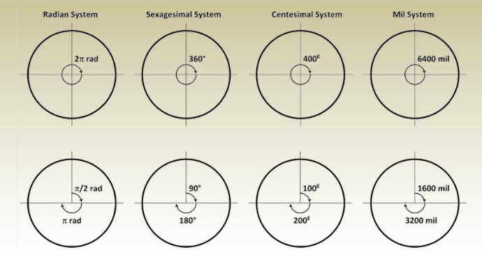
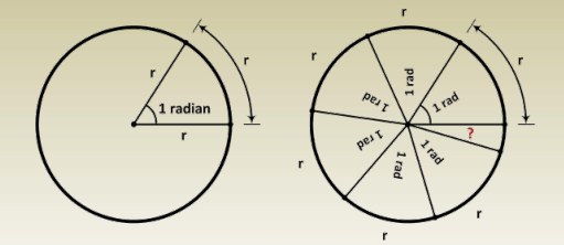
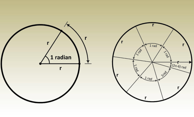
One radian is the angle formed at the center of a circle when the arc length is equal to the radius of the circle.
The circumference of a circle is 2π times the radius r. Therefore, the number of arcs of length r that fit along the circumference of a circle is 2π.
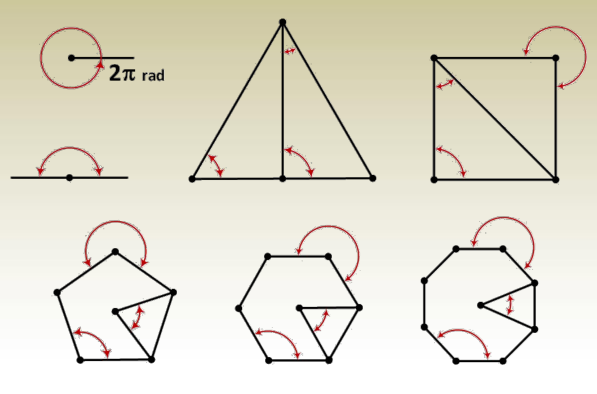
Write the measure of the indicated angles in radians as a
ratio of (all are regular polygons)
Sexagesimal System
This is the most common system for measuring angles. In this system:
- A full circle is divided into 360 degrees (°).
- 1 degree (°) = 60 minutes (‘).
- 1 minute (‘) = 60 seconds (“).
- Example: 36 degrees, 24 minutes, and 52 seconds is written as 36° 24′ 52″.
Conversion Rules
1. Converting Degrees-Minutes-Seconds (DMS) to Decimal Degrees (DD):
Formula:Decimal Degrees=Degrees+Minutes60+Seconds3600\text{Decimal Degrees} = \text{Degrees} + \frac{\text{Minutes}}{60} + \frac{\text{Seconds}}{3600}Decimal Degrees=Degrees+60Minutes+3600Seconds
Example: Convert 37° 45′ 17″ to decimal degrees:37+4560+173600=37+0.75+0.00472222=37.75472222°37 + \frac{45}{60} + \frac{17}{3600} = 37 + 0.75 + 0.00472222 = 37.75472222°37+6045+360017=37+0.75+0.00472222=37.75472222°
2. Converting Decimal Degrees (DD) to Degrees-Minutes-Seconds (DMS):
Steps:
- Degrees: Integer part of the decimal degree.
- Minutes: Multiply the decimal part by 60, take the integer.
- Seconds: Multiply the remaining decimal by 60.
Example: Convert 37.75472222° to DMS:
- Degrees = 37°
- Minutes = (37.75472222 – 37) × 60 = 45.28333333 → 45′
- Seconds = (45.28333333 – 45) × 60 = 17″
Result: 37.75472222°=37°45′17″\text{Result: } 37.75472222° = 37° 45′ 17″Result: 37.75472222°=37°45′17″
In DMS format, only seconds can have a decimal portion.
Centesimal System
- Also known as the metric system of angular measurement.
- A full circle is divided into 400 grads (g).
- Each grad is subdivided into:
- Centigrads (c) – equivalent to centesimal minutes.
- Centicentigrads (cc) – equivalent to centesimal seconds.
Example: Convert 36.123450 g to grads, centigrads, and centicentigrads:36.123450g=36g12c34.5cc36.123450 g = 36 g 12 c 34.5 cc36.123450g=36g12c34.5cc
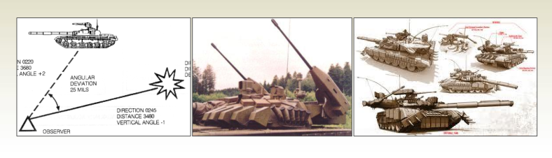
Mil System
- Primarily used in military and artillery calculations.
- A full circle is divided into 6400 mils (mil).
Conversion between Measures of Angles
The presented systems are:

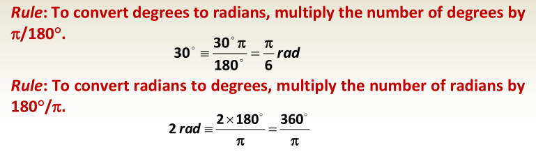
Radians and degrees
- 2 rad = 360°
- rad = 180°
Dividing both sides gives
1 rad = 180°/ = 57.2957795…°
Or dividing both sides of previous equation by 180°
1° = /180° rad = 0.01745329… rad
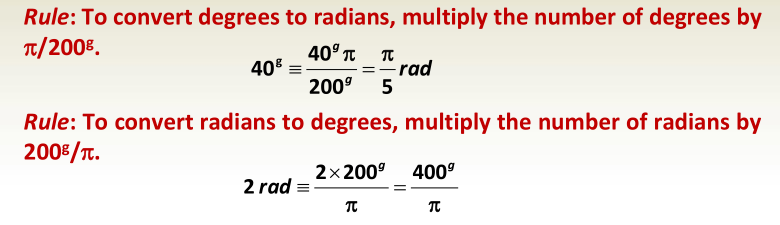
Radians and grads
- 2 rad = 400 g
- rad = 200 g
Dividing both sides gives
1 rad = 200 g / = 63.6619772… g
Or dividing both sides of previous equation by 200 g
1 g = /200 g rad = 0.01570796326… rad
Angles in Surveying
In surveying, angles are measured between a line and a reference plane or a reference line to determine direction, elevation, or position.
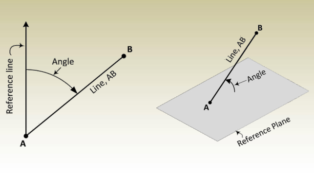
Components of an Angle
In surveying, three components need to be known to describe an
angle. These parts are:
- Reference or starting line.
- Sense of turning, and
- Magnitude (value of the angle).
For surveying works three types of angles are
measured, mainly: horizontal, vertical, and zenith
angles.
Horizontal Angles
Reference Line: Horizontal directions use a meridian as the reference
line.
- Meridians are lines, on the mean surface of the earth, that join the
north and south poles.
Horizontal Angles: Reference Line
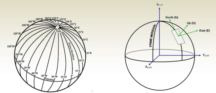
For plane surveying, a rectangular coordinate system is defined as follows:
- origin on the point,
- the Y-axis pointing to north direction (the meridian
passing through the point), - X-axis pointing to east direction, while
- Z-axis points towards the up
direction which is the direction of
gravity at this point.
This coordinate system is called
Northing-Easting-Up instead of X-Y-Z
and is abbreviated as ENU.
The North-South axis of the ENU system
(or the meridian) is the reference for
horizontal directions which are measured
on the EN horizontal plane.
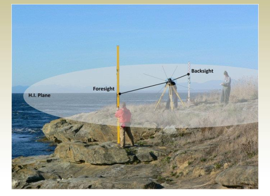
Horizontal Angles: Summary
- Are measured in the horizontal plane
- The left-most line is called Backsight
- The right-most from the backsight is called Foresight
- The intersection of the two lines is usually the point at which an instrument
is set to measure the angle – it is called the Station.
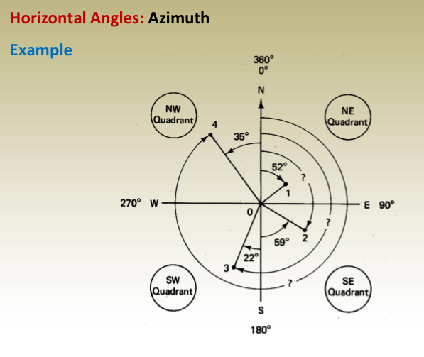
Horizontal Angles: Azimuth
It represents the orientation (direction) of objects in the horizontal
plane and is measured clockwise from the north (meridian) and must
be in the range: 0 < < 360 .

Horizontal Angles: Back azimuth of a Line
Every line has a forward and a backward azimuths; 12 and 21
respectively. The back azimuth of a line 1-2 is the azimuth of line 2-1.
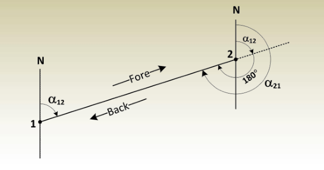
Horizontal Angles: Back azimuth of a Line
The back azimuth of a line may be found by either of two ways:
Adding 180° to the azimuth of the line if the azimuth is less than 180°
or by subtracting 180° from the azimuth of the line if the azimuth is
greater than 180°. Referring to following figure:
- If 12 < 180°, then 21 = 12 + 180°,
- If 12 > 180°, then 21 = 12 – 180°,
Example - for azimuth 40°, the back azimuth = 40° + 180° = 220°
- for azimuth 140°, the back azimuth = 140° + 180° = 320°
- for azimuth 220°, the back azimuth = 220° – 180° = 40°
- for azimuth 320°, the back azimuth = 320° – 180° = 140°
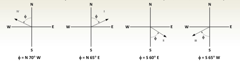
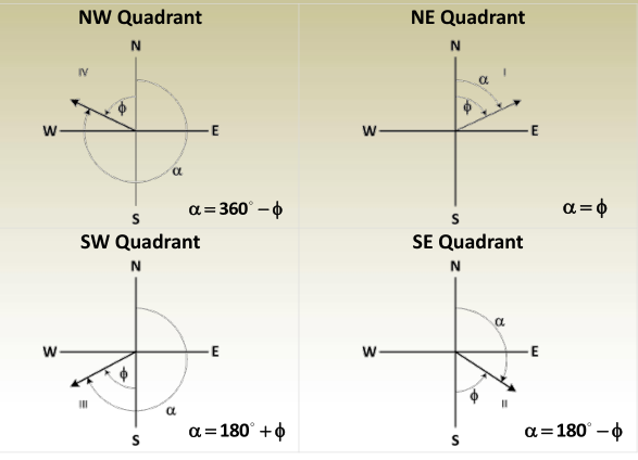
Horizontal Angles: Bearing
- The bearing of a line is the horizontal acute angle between the
meridian and the line with values in the range 0 < < 90 . - Because the bearing of a line cannot exceed 90°, the full horizontal
circle is divided into four quadrants;
northeast (NE), southeast (SE), southwest (SW), and northwest (NW). - Bearing is measured clockwise or counterclockwise from the north
or south end of the meridian and is always accompanied by letters
that locate the quadrant in which the line falls (NE, NW, SE, or SW).
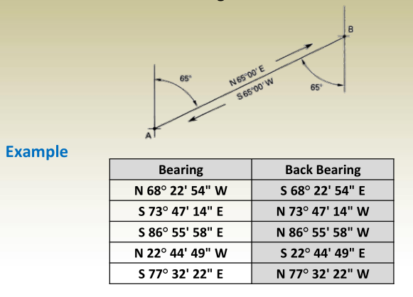
Horizontal Angles: Back Bearing
To reverse a bearing … Reverse the direction letters.
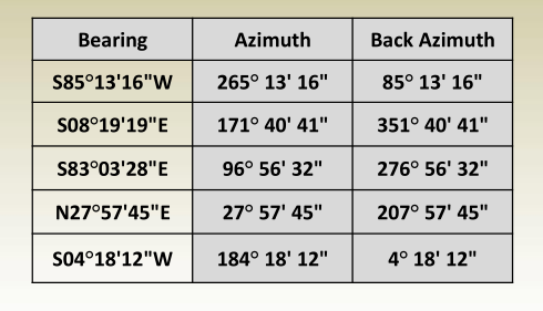
Horizontal Angles: Converting Bearings to Azimuths
The conversion is quadrant dependent as in the following table:
Horizontal Angles: Converting Bearings to Azimuths
Example
Convert the following bearings to azimuths and back azimuths.
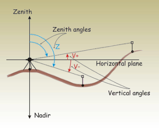
Vertical Angles
- Plumb Line: A vertical line extending from any point on Earth toward the Earth’s center, following the direction of gravity at the observer’s location.
- Zenith: The point on the celestial sphere directly above the observer, where the plumb line intersects.
- Nadir: The point on the celestial sphere directly below the observer, opposite to the zenith.
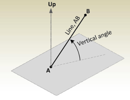
Vertical Angles
- A vertical angle is defined as the angle between the horizontal
plane and the line of object as seen in the figure below. - A zero vertical angle means line AB is in the horizontal plane
Vertical Angles
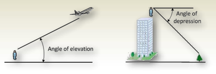
- Above Horizon: 0° to +90°
- Below Horizon: 0° to -90°
- Angle of Elevation: The vertical angle measured upward from the horizontal. It is positive.
- Angle of Depression: The vertical angle measured downward from the horizontal. It is negative.
Zenith Angles
- Measured from the up direction downward to the line,
- A zero zenith angle means vertical direction (pointing upward),
- Range: 0 to 180
- 0 to 90 : above horizon
- 90 to 180 : below horizon
Measurements and Errors
Measurements in Surveying
Definition of a Measurement
A measurement is an observation made to determine an unknown quantity.
Characteristics of Measurements
- No measurement is exact.
- Every measurement contains errors.
- The true value of a measurement is never known.
- The exact size of the errors present is always unknown.
Types of Measurements
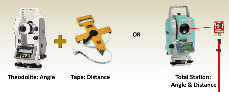
Direct Measurements
- Made by directly applying an instrument to the unknown quantity and observing its value.
- Example:
- Measuring the distance between two points using a graduated tape.
- Measuring an angle using a theodolite or total station.
Indirect Measurements
- Used when direct measurement is not possible or practical.
- The quantity is determined mathematically using direct measurements.
- Example:
- Measuring line lengths and angles to compute station coordinates.
Sources of Errors
1. Instrument Errors
- Caused by imperfections in the construction or adjustment of measuring instruments.
- Example: A tape with unevenly spaced divisions.
2. Environmental Errors
- Caused by changes in atmospheric conditions.
- Example: Temperature variations affecting tape length.
3. Human Errors
- Caused by limitations in human senses and conditions affecting performance.
- Example: Difficulty in reading a micrometer accurately.
Types of Errors
1. Blunders (Gross Errors)
- Caused by human mistakes such as incorrect readings or recording errors.
- Example: Writing 27.55 instead of 25.75.
2. Systematic Errors
- Follow a predictable law and can be corrected.
- Example: Using a tape that is 10 cm short.
3. Random Errors
- Cannot be systematically predicted or corrected.
- Example: Small errors in reading a graduated scale.
Precision vs. Accuracy
Precision
- Degree of consistency between repeated measurements.
- Depends on:
- Instrument sensitivity
- Observer’s skill
Accuracy
- Closeness of a measurement to the true value (which is never exactly known).
- Accuracy is always an estimate since the true value is unknown.
Accuracy of Angle Measurement
Importance of Centering & Leveling
- Theodolites and total stations must be properly centered over a point and leveled.
- This ensures accurate horizontal and vertical angle readings.
Relationship Between Angular & Linear Precision
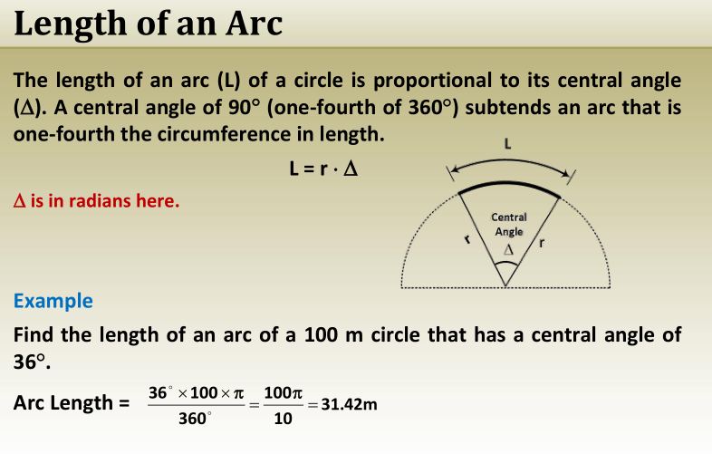
The formula for arc length, radius, and angle:S=r⋅θS = r \cdot \thetaS=r⋅θ
With an angular error dθd\thetadθ, the linear equivalent is:dS=r⋅dθdS = r \cdot d\thetadS=r⋅dθ
Examples of Angular Error Conversions
At a 100 m sighting distance:
- 20″ (arc seconds) → 10 mm error
- 10″ → 5 mm error
- 5″ → 2.5 mm error
- 1″ → 0.5 mm error
Choosing the Right Instrument
- If a 5 mm tolerance is required at 100 m, a 10″ theodolite or total station is necessary.
- If the maximum distance is 50 m, a 20″ instrument is sufficient.
- High-precision instruments (5″, 1″) are only needed for control networks or high-accuracy projects like:
- Dams
- Nuclear Power Plants
Understanding Instrument Accuracy
- Minimum reading ≠ Accuracy
- Always check the manufacturer’s specifications for actual accuracy, not just resolution.
Chapter 4: Distance Measurement
Measuring distances is one of the fundamental concepts in land surveying. In many cases, accurate distance measurement alone is enough to successfully complete a survey project.
Incorrect distance measurements can greatly reduce the reliability and accuracy of the survey data. Therefore, it is essential to choose the most suitable method and equipment to ensure precision in every measurement.
Distance measurement in surveying is rooted in two core principles of geometry:
- A straight line can only be formed between two defined points.
- The shortest path connecting two points is always a straight line.
Mastering distance measurement techniques is crucial for delivering high-quality and professional survey results.
Types of Distances

Horizontal and Slope Distance Measurement
The distance between two points in land surveying can be determined using various techniques, including:
- Pacing
- Odometer wheel
- Taping
- Electronic Distance Measurement (EDM)
- Scaling on a map
Slope Distance or Surface Distance
Slope distance refers to the measurement taken by following the natural contour of the Earth’s surface.
Horizontal Distance
Horizontal distance is the straight-line distance between two points, measured on a perfectly horizontal plane.
- Horizontal distances can either be measured directly or
- Indirectly, by first measuring the slope distance and then converting it to a horizontal measurement.
Electronic Distance Measurement (EDM) Advantage
A major benefit of using EDM devices is that they can measure both slope distance and horizontal distance simultaneously, improving accuracy and efficiency.
Converting Slope Distance to Horizontal Distance
To convert a slope distance into a horizontal distance, you must know:
- The vertical angle (α) of the slope
- The elevation difference (v) between the points
- The slope value, either as a percentage or another format
Mastering these techniques ensures precision in all types of land surveying projects.

Slope to Horizontal Distance
Example
A slope measurement of 791.320 m. The angle measured with a hand
level is 5°30’. Find the horizontal distance H for this slope distance.
Solution
Use the formula
H = S cos
where = 5°30’ 00”
H = S cos 5°30’ 00” = 791.320 (0.9953962) = 787.677 m
Example
A slope distance of 325 m with a difference in elevation of 3.5 m.
Compute the horizontal distance H.
= sin -1 (V/S) = sin -1 (3.5 m/325 m) = = sin -1 (0.01076923077)
= 0 37′ 1.36”
H = 325 cos (0 37′ 1.36”) = 324.981 m
Distance Measurement
Accurate distance measurement is a key part of land surveying. Surveyors use different equipment and techniques depending on the project’s needs and the terrain. Common methods include:
- Pacing
A simple method where distance is estimated by counting steps over a known average stride length. - Odometer Wheel
Also known as a measuring wheel, this tool rolls along the ground to measure distance quickly and efficiently. - Taping
Using a steel or fiberglass tape, surveyors measure distances manually. This method is ideal for short to medium ranges with clear, open terrain. - Electronic Distance Measurement (EDM)
EDM devices use electromagnetic waves to accurately measure both slope and horizontal distances, making them highly effective for long-distance and rugged surveys.
Choosing the right method and equipment is essential for achieving accurate and reliable survey results.

Pacing
Pacing is a basic method of distance measurement where a person counts the number of steps taken to cover a known distance. This technique is often used for quick estimations and error checking.
Advantages of Pacing:
- Very simple to perform
- Does not require any specialized equipment
- Low-tech and cost-effective
- Helpful for estimating distances and verifying large errors when using other measurement methods
Disadvantages of Pacing:
- Accuracy is affected by uneven terrain and topography
- Requires consistent practice to maintain a uniform step length
- Limited to areas where the surveyor can physically walk
- Measures only the surface distance, not the true horizontal distance
Formula for Distance Calculation:
Distance = Number of Steps × Step Length
Pacing is a valuable skill for surveyors, especially when quick distance approximations are needed on-site


When the terrain is open and relatively level, pacing can achieve an accuracy between 1/50 to 1/100 of the total distance.
Example:
A surveyor counts 491 paces over an unknown distance.
The surveyor had earlier calibrated their step length at 0.695 meters.
The expected accuracy for this pacing exercise is 1:60.
Step-by-Step Calculation:
- Measured Distance (L):
L = 491 × 0.695 = 341.245 meters - Expected Error (S):
S = 341.245 ÷ 60 = 5.687 meters
Thus, the final result for the measured distance is:
341.245 meters ± 5.687 meters
This means the actual distance lies within a range of approximately 335.558 meters to 346.932 meters.
Odometer Wheel
An odometer wheel is a mechanical device that records the number of revolutions as it moves along a surface, helping in distance measurement without complex tools.
Advantages of Odometer Wheel:
- Simple and easy to use
- Requires no advanced technology
Disadvantages of Odometer Wheel:
- Surface conditions, like rough or uneven ground, can affect accuracy
- The user must physically traverse the measured distance
- It only measures surface (slope) distance, not true horizontal distance
Distance Calculation Formula:
D (m) = 2 × π × r × N
Where:
- D = Measured distance (meters)
- r = Radius of the wheel (meters)
- N = Number of wheel revolutions
The odometer wheel typically offers better accuracy than pacing, with an expected precision of about 1/200 of the distance measured.
Example:
A bicycle wheel completes 155.2 revolutions as it rolls along the boundary of a field.
The radius of the wheel is 0.350 meters.
- Measured Distance (D):
D = 2 × π × r × N
= (2 × π × 0.350) × 155.2
= 341.303 meters - Expected Error (S):
S = 341.303 ÷ 200
= 1.707 meters
Thus, the final result is:
341.303 meters ± 1.707 meters
This means the true field length lies between approximately 339.596 meters and 343.010 meters.

Tape Measurements
The most accurate traditional method of measuring distances uses a measuring tape.

Taping is a traditional but highly precise method used to measure distances in land surveying, especially over short to medium distances.
Advantages of Taping:
- Delivers high precision in distance measurement
- Suitable for measuring horizontal distances accurately
Disadvantages of Taping:
- Requires multiple people for proper handling and tensioning
- Needs a clear, travelable route free from obstructions
- Achieving high precision demands correction of systematic errors like tape sag, temperature changes, and alignment
When correct procedures are applied, taping can achieve errors less than 1 centimeter over 30 meters, equivalent to an accuracy of approximately 1:3000.
Example:
A distance is measured using a tape and found to be 341.303 meters.
- Expected Error (S):
S = 341.303 ÷ 3000
= 0.114 meters
Thus, the final result is:
341.303 meters ± 0.114 meters
Meaning the true distance lies between approximately 341.189 meters and 341.417 meters.
Standard Equipment for a taping party of three people:

Different location of the zero mark

There are two basic methods of taping: horizontal & slope taping
- Horizontal taping on sloping ground


2. Slope taping

Ranging Poles

- These pins come in sets of 11 pins, carried on a wire ring. Why?
- Used most frequently to keep count of tape increments in measuring long distances.
if you have 6 pins in your hand, how many distances you already marked on the ground?
Plumb Bobs
- When measuring an unknown distance, plumb bobs are used to copy ground points to the tape.

- When placing a known distance on the ground, one ground point is copied to the tape and the other is copied from the tape to the ground.
Systematic Errors in Tape Measurements
While using a tape for distance measurement, several systematic errors can occur. Understanding and correcting these errors is crucial for achieving accurate results.
Types of Taping Errors:
- Tape Length Error:
The actual tape length may differ from the nominal (written) length due to manufacturing variations or wear and tear. - Error Due to Temperature:
Steel tapes expand or contract with temperature changes, affecting distance measurements. - Error Due to Tension Variation:
Field tension during measurement often differs from the factory-calibrated tension, causing minor inaccuracies. - Error Due to Sag:
When a tape is supported only at its ends, it sags due to its own weight, leading to shorter measured distances.
Correction for Tape Length Error
The tape length error is the difference between the working tape length and the standard tape length.
Important Terms:
- Cₗ = Correction to be added to the measured distance due to tape length error
- Lₐ = Actual length of the tape used (in meters)
- Lₙ = Nominal (labeled) length of the tape (in meters)
- D = Measured distance (in meters)
Corrected Distance Formula:
To find the corrected distance (D̂):
Corrected Distance (D̂) = Measured Distance (D) + Correction (Cₗ)
The correction (Cₗ) itself is calculated based on the difference between actual and nominal tape lengths.

Tape Length Error: Example
In the figure if the first tape is a 2 m tape but was 13 cm too short, calculate the corrected distance.
Solution
L n = 2 m,
L a = 2.000 – 0.130 m = 1.870 m
Distance correction:
C L = 0.091 (1.870 – 2.000)/2.000
= -0.006 m
Corrected distance = measured distance + correction
= 0.091 + (-0.006) = 0.085 m
Tape Length Error: Example
In the figure if the third tape is a 2 m tape but was 7.3 cm
too long, calculate the corrected distance.
Solution
L n = 2 m
L a = 2.000 + 0.073 m = 2.073 m
Distance correction:
C L = 0.082 (2.073 – 2.000)/2.000
= 0.003 m
Corrected distance = measured distance + correction
= 0.082 + 0.003 = 0.085 m
Blunders in Tape Measurements
- Incorrect count of the full tapes
- Misreading the tape
- Recording the readings
- Mistaking the end marks
Random Errors in Tape Measurements
- Pin setting
- Tape reading
- Plumbing
Electronic Distance Measurements (EDM)
EDM is a device that measures lengths by indirectly determining the number of full and partial waves of transmitted electromagnetic energy between the two ends of a line.

Advantages of EDM:
- Provides precise distance measurements
- Line of sight instrument, making it ideal for direct, unobstructed paths
- Capable of measuring long distances accurately
- Reflectorless EDM allows for single-person operation, reducing manpower needs
Disadvantages of EDM:
- Relies on batteries for operation, so power management is crucial
- Accuracy can be affected by atmospheric conditions like temperature, humidity, and air pressure
- Expensive, making it less accessible for smaller projects
- Before: EDMs could measure distances only.
- Now: EDMs can measure distances and angles, called total station instruments.
- Accuracies of EDMs are given in two parts;
- the first part is a constant, and
- the second is proportional to the distance measured and given as ppm = parts per million.
- One ppm equals 1 mm/km. In a distance 5000 m long, a 5 ppm error equals 5000 x (5 /1000000) = 0.025 m = 25 mm.
- EDMs are available with precisions that vary from ±(1 mm + 1 ppm) to ±(10 mm + 5 ppm).
Total Stations are advanced surveying instruments that combine multiple functions into one device, making them indispensable in modern surveying tasks.
Components of a Total Station:
- Electronic Distance Measurement (EDM) Unit
- Electronic Angle Measurement Unit (Digital Theodolite)
- Computer for data processing
A total station can automatically measure:
- Horizontal angles
- Vertical angles
- Distances (horizontal, vertical, and slope distances)
The instrument instantly computes and displays horizontal and vertical distance components, eliminating the need for manual calculations. All data can be stored in the instrument or an external data collector.
Errors in Electronic Distance Measurement (EDM)
EDM instruments provide distance measurements with high precision. However, errors can still occur, which affect the accuracy.
Types of Errors in EDM:
- Constant Error:
This error is fixed and remains the same regardless of the distance measured. It is most significant over short distances.
Example: With an EDM instrument having a constant error of ±2 mm, a 20-meter measurement could have an accuracy of only ±2/20,000, or 100 ppm. - Proportional Error:
This error is proportional to the distance being measured. It becomes more significant over longer distances.
For long distances (e.g., 2 km), the constant error becomes negligible, and the proportional error takes precedence.
Major Error Components:
- Instrument Miscentering
- Target Miscentering
- Constant Error
- Proportional Error
Combined Error Calculation in EDM:
The combined error is calculated using the following formula:
- Eᵢ = Miscentering error in the instrument
- Eʳ = Miscentering error in the reflector
- Eᶜ = Constant error for the EDM
- ppm = Proportional error for the EDM
- D = Measured slope distance
Example of EDM Error Calculation:
A slope distance of 827.329 m was measured using an EDM instrument with specified errors of ± (2 mm + 2 ppm). The instrument was centered with an estimated error of ±3 mm, and the estimated target miscentering was ±5 mm. What is the total error in the observed distance?
- Convert the distance to millimeters for consistency: 827.329 m = 827,329 mm
- Apply the specified errors:
- Constant error = ±2 mm
- Proportional error = 2 ppm (2 parts per million of 827,329 mm)
- Solution:
The total error in the observed distance is calculated, resulting in a distance precision of 6.4 mm or better than 1:129,000.
Chapter-5 Leveling
Leveling Areas of Application
- Design of roads, railways, and water channels using modern terrain data
- Layout of construction projects based on digital elevation models
- Accurate calculation of earthwork volumes using Civil 3D tools
- Analysis of site drainage using surface flow paths
- Mapping of land elevation and terrain using contour lines
- Monitoring land subsidence with updated surface comparison tools
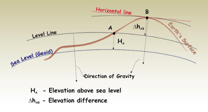
Leveling Basic Terms
- Vertical line: A line that follows the local direction of gravity as indicated by a plumb line.
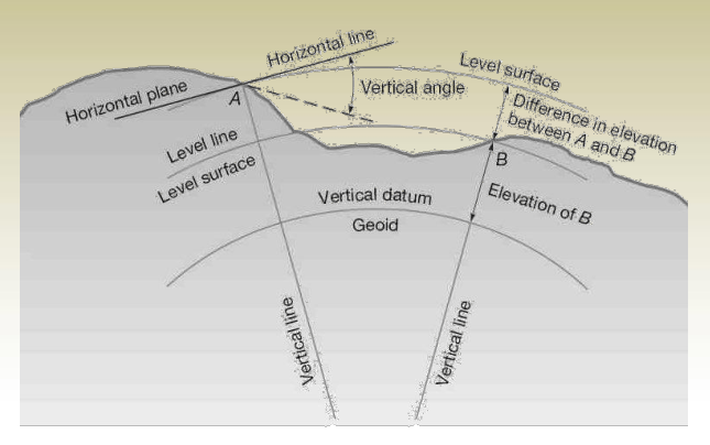
• Vertical Line: A line aligned with the force of gravity, indicated by a plumb line.
• Level Surface: A curved surface where every point is perpendicular to gravity; still water represents this naturally. Also called an equipotential surface.
• Level Line: A curved line lying entirely within a level surface.
• Horizontal Plane: A flat surface perpendicular to the local vertical (gravity direction).
• Horizontal Line: A straight line lying in a horizontal plane, perpendicular to a vertical line.
• Vertical Datum: A reference level surface from which elevations are measured, often assigned an elevation of zero.
• Reference Datum: A base surface used for height comparisons of all measured points.
• Geoid: A specific level surface representing Earth’s mean sea level used as a vertical reference.
• Mean Sea Level (MSL): The average sea level measured over a 19-year period, used as a common elevation datum.
• Elevation: The vertical distance from a point to the datum surface (e.g., if Point A = 802.46 m, it’s 802.46 m above the datum).
• Benchmark (BM): A fixed, marked point with a known or assumed elevation used as a reference in surveying.
• Vertical Control: A network of benchmarks with known elevations across a region, used for height accuracy.
• Leveling: The method of measuring elevation differences between points on the ground.
Earth Curvature and Refraction
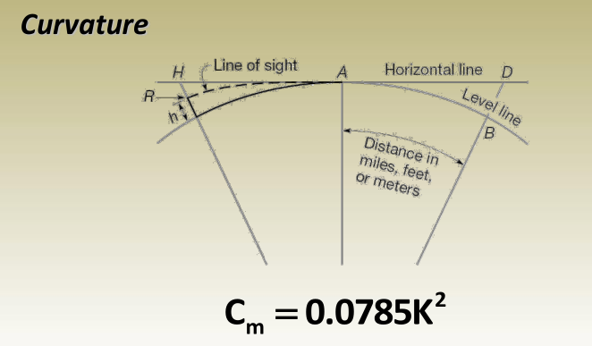
Where C m is the deviation meters (distance BD) while K is the distance AB in kilometers.
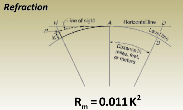
Where R m is the refraction in meters (distance RH) while K is the same as that in curvature effect calculations.
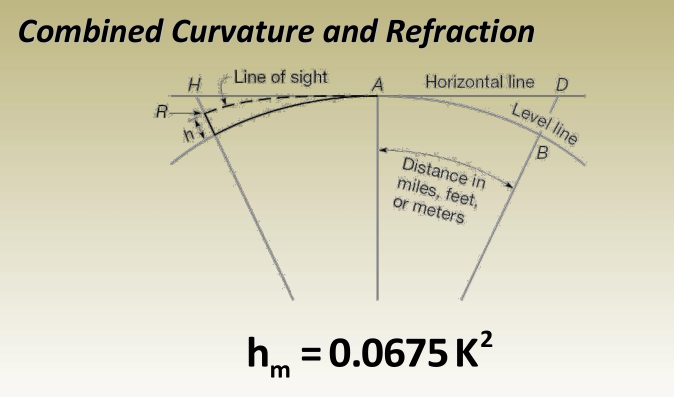
Where h m is the combined effect of curvature and refraction in meters while K is the distance in kilometers.
Yahan aapke uploaded image ka written text format diya gaya hai jo aap easily copy kar sakte hain:
Example
d = 100 m:
Curvature correction:
Cm=0.0785k2=0.0785(1001000)2=0.0785(110)2=0.000785 m=0.785 mmC_m = 0.0785k^2 = 0.0785 \left(\dfrac{100}{1000}\right)^2 = 0.0785 \left(\dfrac{1}{10}\right)^2 = 0.000785 \, \text{m} = 0.785 \, \text{mm}
Refraction correction:
Rm=0.011k2=0.011(1001000)2=0.011(110)2=0.00011 m=0.11 mmR_m = 0.011k^2 = 0.011 \left(\dfrac{100}{1000}\right)^2 = 0.011 \left(\dfrac{1}{10}\right)^2 = 0.00011 \, \text{m} = 0.11 \, \text{mm}
Combined correction:
hm=0.785−0.110=0.675 mmh_m = 0.785 – 0.110 = 0.675 \, \text{mm}
Or using the formula:
hm=0.0675 k2=0.0675×(1001000)2=0.000675 m=0.675 mmh_m = 0.0675 \, k^2 = 0.0675 \times \left(\dfrac{100}{1000}\right)^2 = 0.000675 \, \text{m} = 0.675 \, \text{mm}
d = 40 km, the curvature correction
Curvature correction:
Cm=0.0785k2=0.0785(40)2=0.0785×1600=125.6 mC_m = 0.0785k^2 = 0.0785(40)^2 = 0.0785 \times 1600 = 125.6 \, \text{m}
Refraction correction:
Rm=0.011k2=0.011×402=0.011×1600=17.6 mR_m = 0.011k^2 = 0.011 \times 40^2 = 0.011 \times 1600 = 17.6 \, \text{m}
Combined correction:
hm=125.6−17.6=108 mh_m = 125.6 – 17.6 = 108 \, \text{m}
Or using the formula:
hm=0.0675 k2=0.0675×402=108 mh_m = 0.0675 \, k^2 = 0.0675 \times 40^2 = 108 \, \text{m}
Types of Leveling
• Taping
Direct method of measuring height differences by using graduated tapes over short distances.
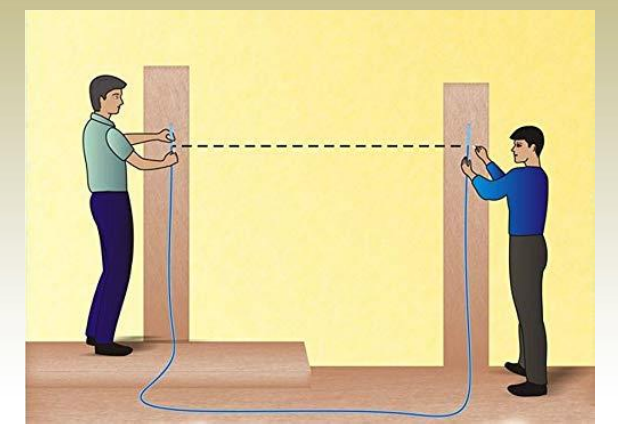
• Hydrostatic Leveling
A highly accurate method based on the principle that fluid levels in connected containers remain equal, used for sensitive elevation measurements.
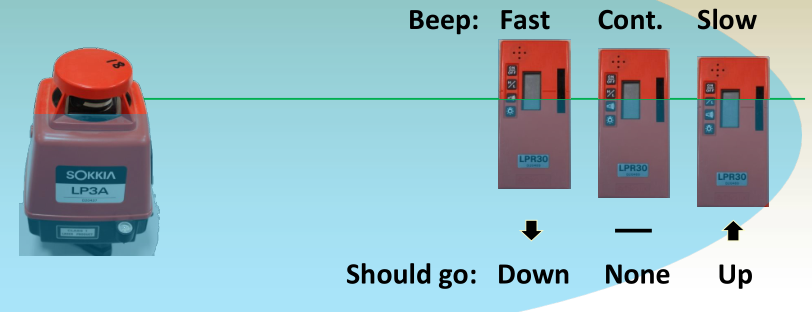
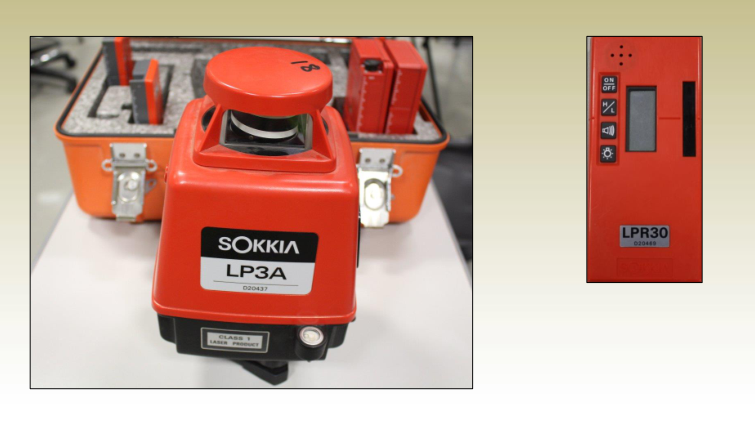
• Laser Leveling
Utilizes a rotating laser beam to establish a constant reference plane, ensuring high-precision leveling in all directions.
• Trigonometric Leveling
Calculates elevation difference using a measured slope distance and the vertical angle between two points.
• Differential Leveling
Involves using a leveling instrument and leveling rods to determine height difference by subtracting the back and foresight readings.
Hydrostatic Leveling
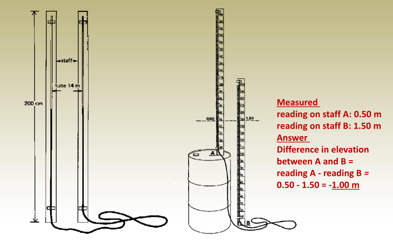
Copying the level of sockets around a room
Laser Leveling
- Laser levels contain a rotating laser which defines a visible horizontal plane from which distance to the ground can be made and then the height can be determined.
Elevation calculation
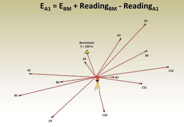
Example Uses

Trigonometric Leveling
Vertical distance V may be obtained from
V = S sin
- If the horizontal distance H is known:
V = H tan - Due to curvature and refraction, the above equations
are valid as shown only for ranges of 100 m or less: - For distances greater than 100 m, the curvature and
refraction correction, h m , must be added, resulting in
V = S sin + h m = S sin + 0.0675 (S cos ) 2
V = H tan + h m = H tan + 0.0675 H 2
Yahan aapka diya gaya content copyright-free aur modern style mein likha gaya hai, user-friendly aur SEO-optimized format ke sath:
Example – Trigonometric Leveling
In the given scenario, the slope distance between two points A and B is 3501.986 meters, and the slope angle (α) is +4°37’25”. Under standard atmospheric conditions, determine the elevation difference between the EDM device at point A and the reflector at point B.
Step-by-Step Solution:
- Horizontal Distance (H):
H=S⋅cos(α)=3501.986⋅cos(4∘37′25″)=3490.590 mH = S \cdot \cos(\alpha) = 3501.986 \cdot \cos(4^\circ 37’25”) = 3490.590 \, \text{m} - Curvature and Refraction Correction (hₘ):
hm=0.0675⋅(3490.5901000)2=0.0675⋅(3.49059)2=0.822 mh_m = 0.0675 \cdot \left(\dfrac{3490.590}{1000}\right)^2 = 0.0675 \cdot (3.49059)^2 = 0.822 \, \text{m} - Vertical Elevation Difference (V):
V=S⋅sin(α)+hm=3501.986⋅sin(4∘37′25″)+0.822V = S \cdot \sin(\alpha) + h_m = 3501.986 \cdot \sin(4^\circ 37’25”) + 0.822
V=282.294+0.822=283.116 mV = 282.294 + 0.822 = 283.116 \, \text{m}
Key Requirements for Trigonometric Leveling:
- Accurate angle measurement using a Theodolite or Total Station
- Distance measurement using a measuring tape or EDM-enabled Total Station
Elevation Difference Calculations Using Trigonometric Leveling
For Distances Less Than 100 m:
To find the elevation of point B, use:
EB=EA+hi+V−rE_B = E_A + h_i + V – r
Where:
- EAE_A = Elevation of point A
- hih_i = Instrument height
- VV = Vertical difference
- rr = Rod (reflector) height
For Distances Greater Than 100 m:
Use:
EB=EA+hi+∣V+hm∣−rE_B = E_A + h_i + |V + h_m| – r
Where hmh_m = Curvature and refraction correction.
Example 1
- Given:
Slope distance = 2923.504 m
Zenith angle = 81°42’20”
EA=377.718 mE_A = 377.718 \, \text{m}
Instrument height = Rod height = same - Solution:
- Horizontal distance:
H=S⋅sin(z)=2923.504⋅sin(81∘42′20′′)=2892.924 mH = S \cdot \sin(z) = 2923.504 \cdot \sin(81^\circ 42’20”) = 2892.924 \, \text{m} - Curvature and refraction correction:
hm=0.0675⋅(2892.9241000)2=0.565 mh_m = 0.0675 \cdot \left(\frac{2892.924}{1000}\right)^2 = 0.565 \, \text{m} - Vertical difference:
V=S⋅cos(z)=2923.504⋅cos(81∘42′20′′)=421.745 mV = S \cdot \cos(z) = 2923.504 \cdot \cos(81^\circ 42’20”) = 421.745 \, \text{m} - Since instrument height = rod height:
EB=EA+∣V+hm∣=377.718+422.310=800.028 mE_B = E_A + |V + h_m| = 377.718 + 422.310 = 800.028 \, \text{m}
- Horizontal distance:
Example 2
- Given:
EA=446.014 mE_A = 446.014 \, \text{m},
Reflector height at A = 1.632 m,
Reflector height at B = 2.663 m- Point A:
Slope distance = 2581.282 m
Slope angle = -10°26’20” - Point B:
Slope distance = 3622.696 m
Slope angle = -6°42’54”
- Point A:
- Solution: Point A Vertical Difference: VA=∣SA⋅sin(αA)+0.0675⋅(SA⋅cos(αA)1000)2∣V_A = |S_A \cdot \sin(\alpha_A) + 0.0675 \cdot \left(\frac{S_A \cdot \cos(\alpha_A)}{1000}\right)^2|
=∣−467.669+0.435∣=467.234 m= |-467.669 + 0.435| = 467.234 \, \text{m} Point B Vertical Difference: VB=∣SB⋅sin(αB)+0.0675⋅(SB⋅cos(αB)1000)2∣V_B = |S_B \cdot \sin(\alpha_B) + 0.0675 \cdot \left(\frac{S_B \cdot \cos(\alpha_B)}{1000}\right)^2|
=∣−423.604+0.874∣=422.730 m= |-423.604 + 0.874| = 422.730 \, \text{m} Elevation of Point B: EB=EA+rA+VA−VB−rBE_B = E_A + r_A + V_A – V_B – r_B
=446.014+1.632+467.234−422.730−2.663=489.487 m= 446.014 + 1.632 + 467.234 – 422.730 – 2.663 = 489.487 \, \text{m}
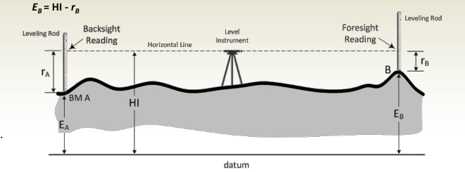
Differential Leveling – Basic Method
Used to find elevation difference between two points.
Procedure:
- Set up the leveling instrument between two points (e.g., BM A and point B).
- Take a backsight (BS) reading rAr_A on the benchmark.
- Calculate Height of Instrument (HI):
HI=EA+rAHI = E_A + r_A - Take a foresight (FS) reading rBr_B on point B.
- Calculate elevation of point B:
EB=HI−rBE_B = HI – r_B
- After the instrument is leveled it will rotate on a horizontal plane
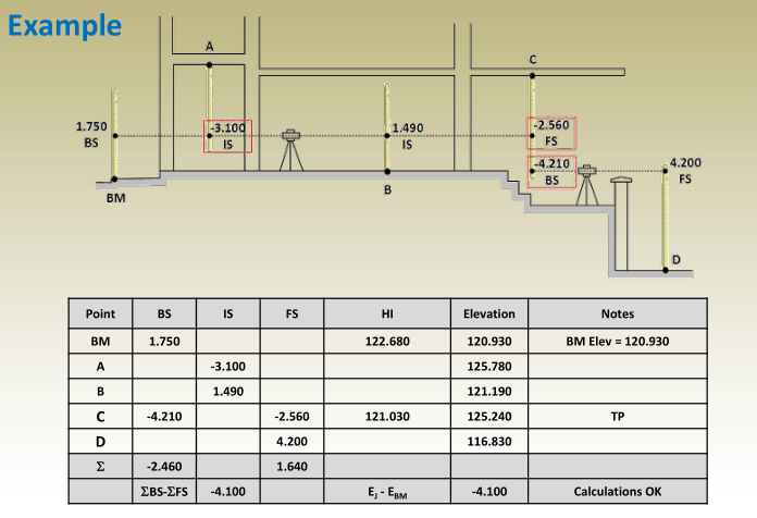
Example – Finding Elevation of a Point Using Differential Leveling
Given:
- Elevation of benchmark (BM1):
EBM1=250.100 mE_{BM1} = 250.100 \, \text{m} - Backsight on BM1:
BSBM1=2.568 mBS_{BM1} = 2.568 \, \text{m} - Foresight on point X:
FSX=0.366 mFS_X = 0.366 \, \text{m}
Solution:
- Calculate Height of Instrument (HI): HI=EBM1+BSBM1=250.100+2.568=252.668 mHI = E_{BM1} + BS_{BM1} = 250.100 + 2.568 = 252.668 \, \text{m}
- Find Elevation of Point X: EX=HI−FSX=252.668−0.366=252.302 mE_X = HI – FS_X = 252.668 – 0.366 = 252.302 \, \text{m}
Differential Leveling Instruments
Level – Instrument for Measuring Elevation Differences
A level is a surveying instrument used to measure height differences between points. It typically includes the following components:
- Telescope: For sighting distant objects.
- Rifle Sight: Helps with rough aiming.
- Leveling Device: Includes a circular bubble or tubular level, along with three leveling screws for precise setup.
- Slow-Motion Screw: Used for fine adjustment of the instrument’s direction.
- Crosshairs: Located inside the telescope to help align the view with the target.
- Focus Screws: One for adjusting the sharpness of the target, and another for focusing the crosshairs.
Types of Levels
Different types of leveling instruments vary mainly in how they maintain a horizontal line of sight.
Automatic Level:
Most modern levels are automatic, meaning they contain a compensator mechanism that adjusts minor tilts automatically. This ensures the line of sight remains perfectly horizontal without manual correction.
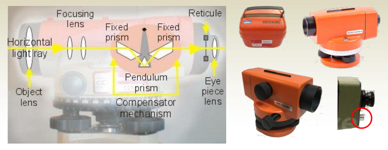
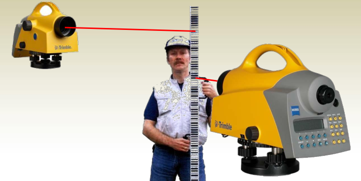
Digital (Electronic) Level
- Uses bar-code graduated staff and laser beam to measure the elevation difference.
- Can also be used as a regular auto level.
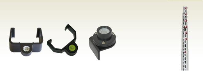
Accessories:
- Leveling Staffs (Rods):
- Graduated in feet or meters or bar code
- Made from wood with or without polymer coating, aluminum, or invar
- Folding, fixed, or telescopic
- Some models have circular bubble attached.
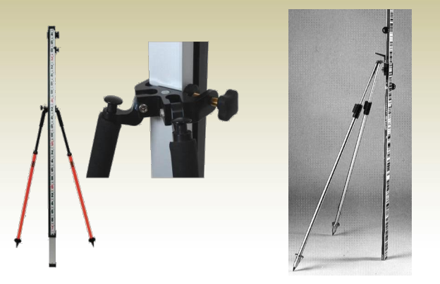
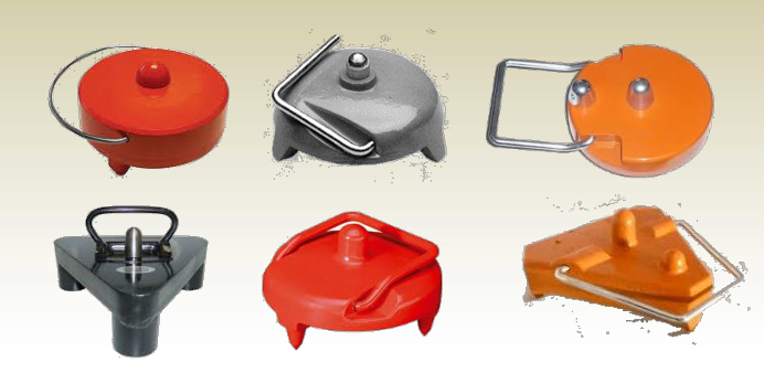
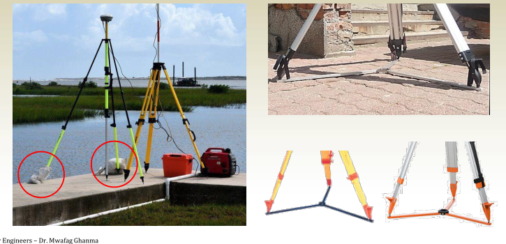
Dual strut: provides quick setup and stable support.
- Ground Plates: improve the accuracy of leveling jobs in soft grounds.
- Tripods: wooden or aluminum, with telescopic or fixed legs
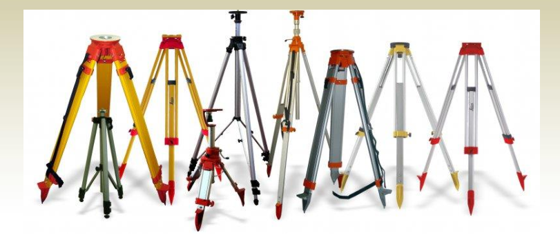
- Tripod Star
provides a stable position of the tripods on smooth and slippery surfaces,
Sighting the leveling rod
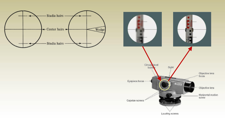
Distance measurement using stadia hairs:
- HD = c * i where i is the stadia spacing (Top –
Bottom), c is the telescope multiplier (mostly = 100) - HD A = i A * 100
- HD B = i B * 100
Precise leveling using stadia hairs:
- Instead of reading BS and FS on the central hair only
- Read the BS on the top, center, and bottom and find the
average BS,
BS avg = (BS top + BS center + BS Bottom )/3 - Read the FS on the top, center, and bottom and find the
average FS,
FS avg = (FS top + FS center + FS Bottom )/3 - Calculate the height of the instrument as
HI avg = E BM + BS avg - Calculate the elevation of the unknown point as
E X = HI avg – Fs avg
Holding the Leveling Rod

Reading the rod

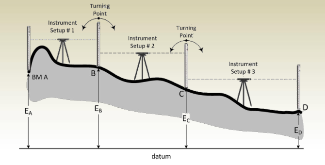
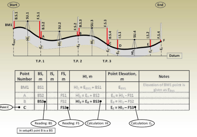
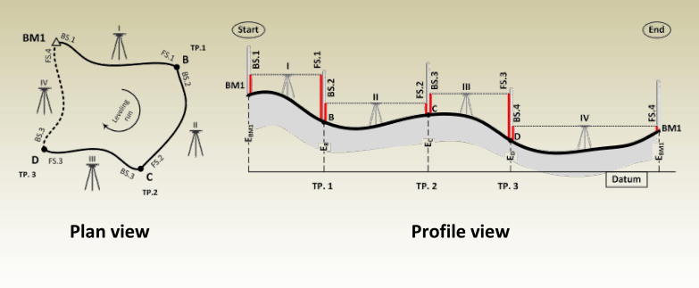
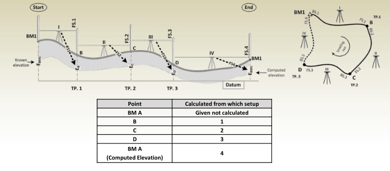
Differential Leveling Procedure
Multi-setup leveling
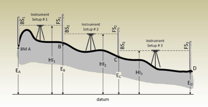
- From setup #1, BS 1 and FS 1
are read then , HI 1 and E B
are calculated as:
HI 1 = E A + BS 1
E B = HI 1 – FS 1 - After moving the instrument to setup #2, BS 2 and FS 2 are read then
HI 2 and E C are calculated as:
HI 2 = E B + BS 2
E C = HI 2 – FS 2 - Finally, with the instrument at setup #3, BS 3 and FS 3 are read, HI 3
and E D are calculated as:
HI 3 = E C + BS 3
E D = HI 3 – FS 3
Turning Points
- Points B and C are called Turning or Change Points since they were used in two successive setups.
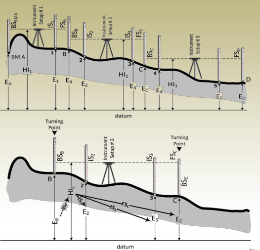
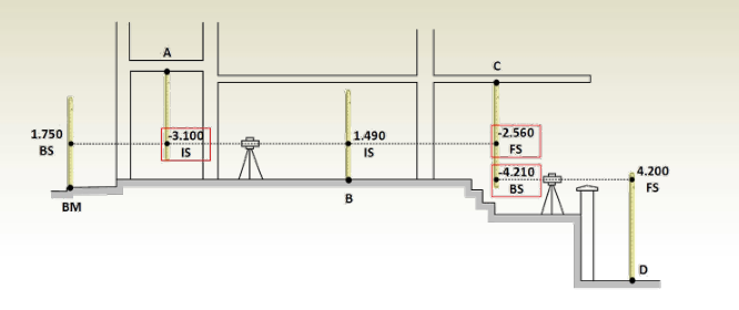
Intermediate Sights
HI 2 = E B + BS B
From which
E 2 = HI 2 – IS 2
E 3 = HI 2 – IS 3
E C = HI 2 – FS C
Types of Sight in Leveling
During leveling operations, different types of readings are taken depending on the purpose and position of the instrument. These include:
- Backsight (B.S.):
This is the first reading taken after setting up the instrument. It is recorded at a point with a known elevation, such as a benchmark. It helps establish the instrument height (HI). - Foresight (F.S.):
This is the final reading taken from the current instrument position. It is usually taken on a point where the elevation is to be determined before moving the instrument to a new location. - Intermediate Sight (I.S.):
These are readings taken between the backsight and foresight. They are used to determine elevations of other points without moving the instrument.
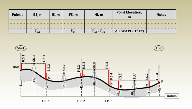
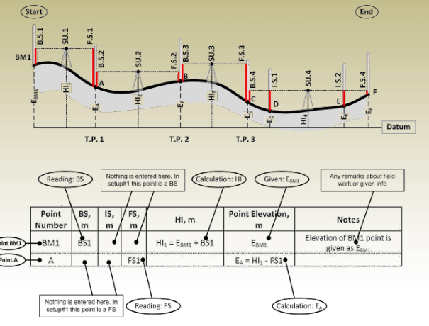
Tabulation of Leveling Measurements and Computations
Setup #1
Setup #2

Setup #3
Setup #4
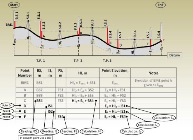
Complete table
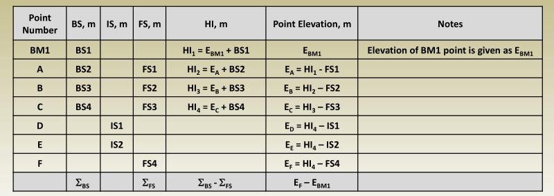
Important notes:
- Each point in the table has one line in the table.
- Points A, B, and C are turning points. Turning points in the table have two readings; a BS reading from one setup and FS reading from the next setup.
- Intermediate points have one reading for each one which is its IS.
- Calculations check must be done to avoid any computational errors.
Inverted Staff
- Used to determine the elevation of a point above the line of sight of the instrument, e.g., ceilings, underside of a bridge (soffits), balcony etc.
- As the name suggests, the staff is simply turned upside –down, the bottom ( zero point) is placed against the point that the level is required, and then read.
Open and Closed Leveling
Leveling Calculations & Error Checking
- Check in Leveling Tables:
Leveling tables help verify arithmetic accuracy only. They don’t detect major mistakes in field readings. - Error Possibility in Readings:
If leveling is done in one direction only (open leveling), any significant error in a backsight or foresight reading may go unnoticed. - Accurate Check Requirement:
To ensure fieldwork accuracy, the leveling line must either:- Return to the starting benchmark, or
- End at a different benchmark.
This is called closed leveling.
Types of Leveling
Open Leveling
- Starts at a known elevation point (benchmark).
- Ends at a point of unknown elevation.
- Disadvantage: No method to check accuracy.
- Recommendation: Should generally be avoided.
Closed Leveling
- Starts and ends at known elevation points.
- Ensures accuracy verification of fieldwork.
- Preferred method in most surveying projects.
Types of Closed Leveling:
- Polygon Type:
- Starts and ends at the same benchmark.
- Link Type:
- Starts at one benchmark and ends at a different benchmark.
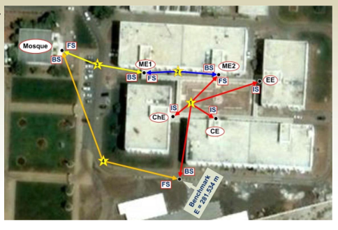
Example: Polygon
In the figure below, the readings were as follows:
- Setup 1: BS=1.701, IS(CE)=1.349, IS(ChE)=1.433, IS(EE)=1.257, FS(ME2)=1.302,
- Setup 2: BS=1.426, FS=1.325,
- Setup 3: BS=1.124, FS=1.354,
- Setup 4: BS=1.322, FS=1.253,
- Construct and fill a field notes table that represents the field work
- Calculate all point elevations and HI.’s.
- Check your calculations in the table
Closure Error
Errors in Leveling Observations
- Every sight taken includes a small random error.
- Some of these errors cancel each other, while others accumulate.
- Error accumulation depends on:
- The precision of the instrument,
- The care with which readings are taken,
- The total number of readings/setups.
Cumulative Error Behavior
- Cumulative error is proportional to:
- √(number of instrument setups)
- √(total distance run)
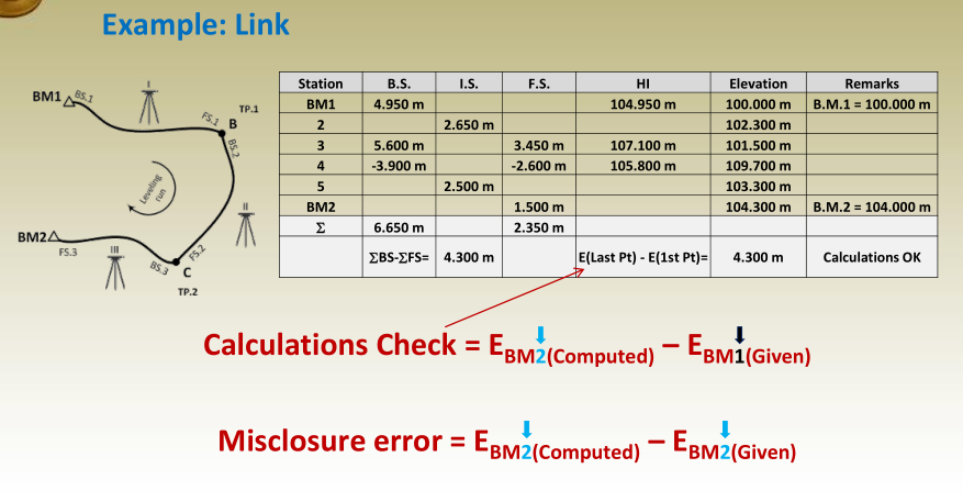
Closure or Misclosure Error
To evaluate the accuracy of a leveling loop, the misclosure error is calculated as:
Misclosure = EBM (Computed) – EBM (Given)
This value tells you how far off your calculated elevation is from the known elevation and helps identify how accurate your survey was.
Maximum Allowable Closure Error
Most countries have standards for the maximum allowable misclosure in leveling work, based on three accuracy classes:
- First Order – Highest precision
- Second Order – Medium precision
- Third Order – Lower precision (general surveys)
Formula:
Cmm = C × √K
- Cmm = maximum allowable misclosure in millimeters
- C = constant depending on required accuracy
- K = total distance run in kilometers
Smaller C values indicate more precise standards, usually used in high-accuracy surveys.
Note:
For U.S. standards, different C values are used for first-, second-, and third-order leveling. A typical chart or table can be referred to for exact values during project planning.
Example 1: Maximum Allowable Closure Error
Question:
What is the maximum allowable closure error for:
- A first-order, class II leveling run that is 20 km long?
- A third-order leveling run of the same 20 km?
Solution:
The formula is:
Cmm = C × √K
Where:
- Cmm = Maximum allowable misclosure in mm
- C = Constant depending on accuracy class
- K = Distance in kilometers
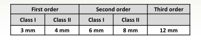
| Order | Class | C Value |
|---|---|---|
| First | Class II | 4.0 |
| Third | — | 12.0 |
For First-order, Class II: C=4.0,K=20 kmC = 4.0,\quad K = 20\text{ km} Cmm=4.0×√20≈4.0×4.472=17.89 mmC_{mm} = 4.0 × √20 ≈ 4.0 × 4.472 = 17.89 \text{ mm}
➡ Maximum allowable error = 17.89 mm
For Third-order: C=12.0,K=20 kmC = 12.0,\quad K = 20\text{ km} Cmm=12.0×√20≈12.0×4.472=53.66 mmC_{mm} = 12.0 × √20 ≈ 12.0 × 4.472 = 53.66 \text{ mm}
➡ Maximum allowable error = 53.66 mm
Example 2: Determine Accuracy Class from Misclosure
Question:
A 16 km closed leveling loop gave a misclosure of 17 mm. What order and class of accuracy does this meet?
Solution:
We need to find the C value using:
C = \frac{\text{Misclosure}}{√K} = \frac{17}{√16} = \frac{17}{4} = 4.25
]
➡ Compare this C = 4.25 with standard table:
| Order | Class | C Value |
|---|---|---|
| First Order | Class II | 4.0 |
| Second Order | Class I | 5.0 |
➡ C = 4.25 lies between First-order Class II and Second-order Class I
Answer:
✔️ The leveling work meets accuracy between First-order Class II and Second-order Class I.
Adjustment of Level Circuits
Closure Correction in Leveling
- This method is applied to closed loop or link leveling circuits.
- The cumulative error in leveling increases with the square root of the number of instrument setups.
- When distributing the closure correction, it should be proportional to the number of setups in each section of the leveling line.
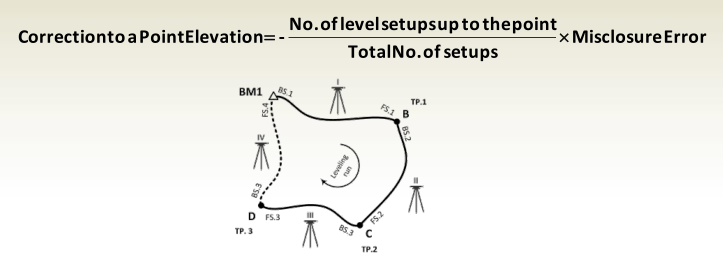
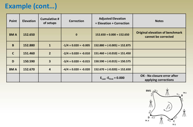
Example (cont…)
- Compute and apply corrections on point elevations to
cancel the misclosure error.
- Total number of setups = 4
Example: Checking Allowable Misclosure for Third-Order Leveling
Problem:
For a leveling line that is 4000 meters (4 km) long and intended for a third-order precision network, determine if the 20 mm misclosure from the previous calculation is acceptable.
Solution:
- According to standards, the maximum allowable closure error is calculated using: Maximum Allowable Error=C×K\text{Maximum Allowable Error} = C \times \sqrt{K} where:
- C=12 mmC = 12 \, \text{mm} (for third-order work),
- K=40001000=4 kmK = \frac{4000}{1000} = 4 \, \text{km}
- So, Maximum Allowable Error=12×4=12×2=24 mm\text{Maximum Allowable Error} = 12 \times \sqrt{4} = 12 \times 2 = 24 \, \text{mm}
- The actual misclosure is 20 mm, which is less than 24 mm, so it is within allowable limits.
Conclusion:
Yes, the misclosure of 20 mm is acceptable for third-order accuracy, and the adjustment can be applied.
Important Points to Consider
- Modified Rod Length:
If someone cuts 0.030 m off the bottom of the leveling rod as a joke, all readings taken with that rod will show values that are 0.030 m higher than the actual elevations. This introduces systematic error and must be corrected. - Rod Shrinkage:
A wooden leveling rod may shrink over time. For example, if it becomes 3.990 m instead of 4.000 m, all readings will be slightly off. It’s important to regularly check the rod’s actual length to ensure accuracy. - Unknown Benchmark Elevation:
In some cases, leveling starts from a point where the elevation is not initially known, and it is determined or assigned later. Such points should be clearly labeled in the field notes, like “BM elevation unknown – to be updated later” to avoid confusion.
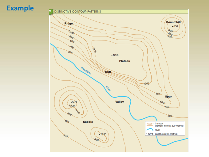
Chapter 6 Contouring
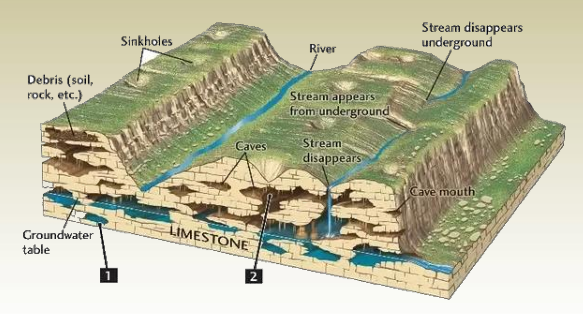
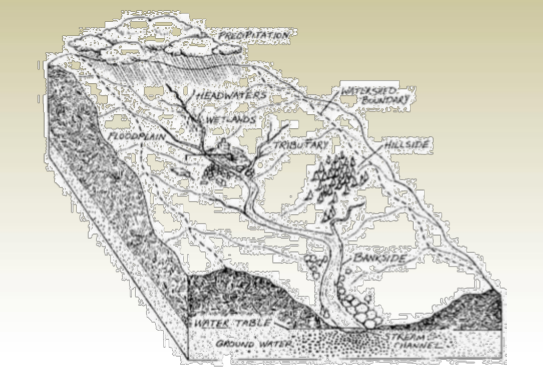
Contouring
- Topography describes the form and features of the Earth’s surface, including natural elevations and depressions.
- Topographic maps are designed to show elevation details along with the horizontal positions of physical and man-made features.
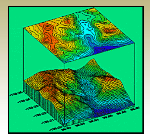
- A common way to represent terrain on maps is by using contour lines, which connect points of equal elevation. Today, modern tools like drones, LiDAR, and GIS software make it easier and more accurate to generate these contours compared to traditional surveying methods.
The process of graphically representing ground topography of natural surface when the ground extends in two directions (X&Y).
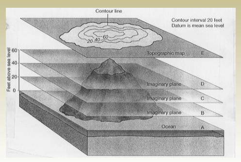
A contour line is an imaginary line that connects points of equal elevation.
Contour Interval
- The vertical gap between two adjacent contour lines is called the contour interval.
- A smaller contour interval provides more detailed information about the ground’s elevation changes.
- However, smaller intervals also mean higher surveying costs, as more measurements and precision are required.
Contour Interval Selection
Key Factors to Consider When Choosing a Contour Interval:
- Purpose and coverage of the map — what the map is meant to show and how large the area is.
- Level of vertical accuracy required for the project.
- Map scale — smaller scales typically use larger contour intervals.
- Terrain type — whether the land is mountainous, hilly, undulating, or flat.
- Surveying cost and time — tighter intervals increase both.
- Clarity of the map — very small intervals may lead to a cluttered or unreadable layout.
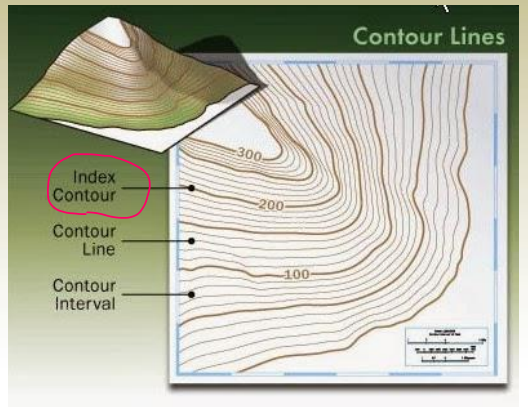
Characteristics of Contour Lines
- All points on the same contour line have the same elevation.
2. All points on the same contour line have the same elevation. Index contour line.
3. The ground slope between contour lines is assumed to be uniform.
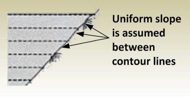
This assumption allows interpolating for elevations for points between contour lines.
X/20 = 3/4
X = 15 m
E P = 15 + 20 = 35 m
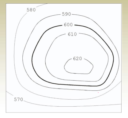
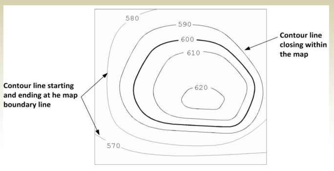
4. Contour lines must close, not necessarily in the limits of the map.
- In case lines do not close within the map, they will start at a
boundary line and end at a boundary line.
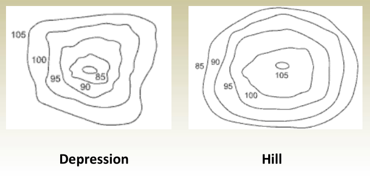
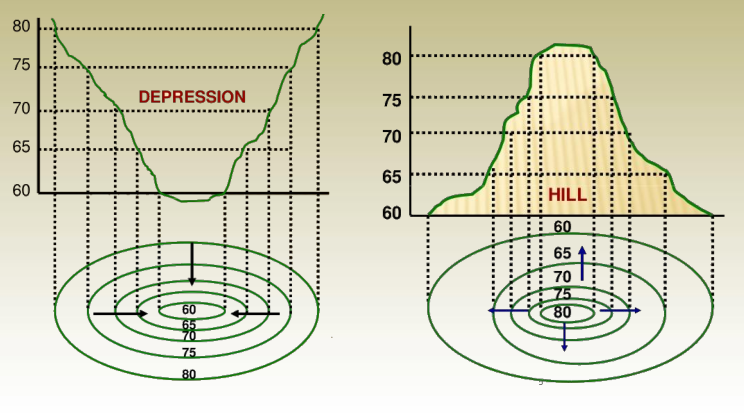
5. Depressions and hills look the same. One must note the contour values to distinguish the terrain.
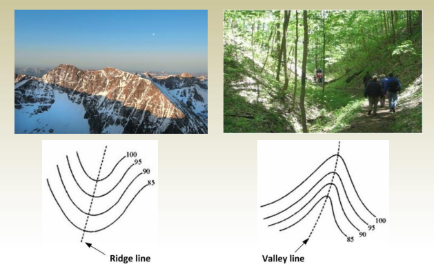
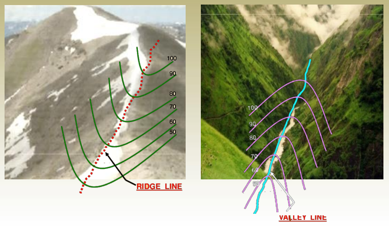
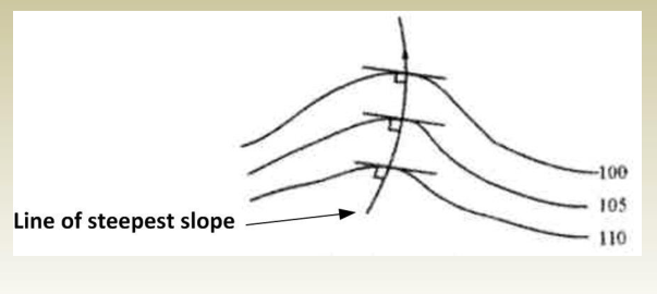
6. Contours deflect uphill at valley lines and downhill at ridge lines.
7. direction of the steepest slope at a point on the contour is at right angles to the contour.
8. Irregular contours indicate uneven surface
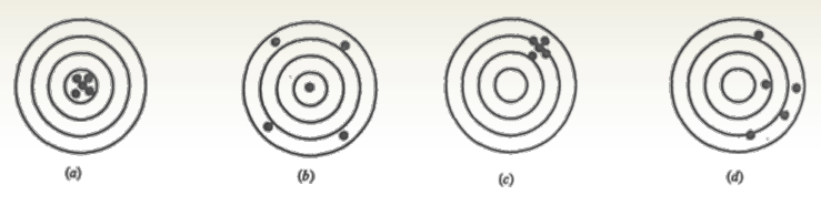
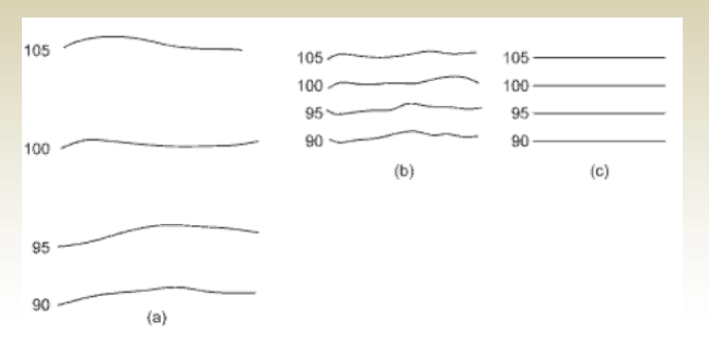
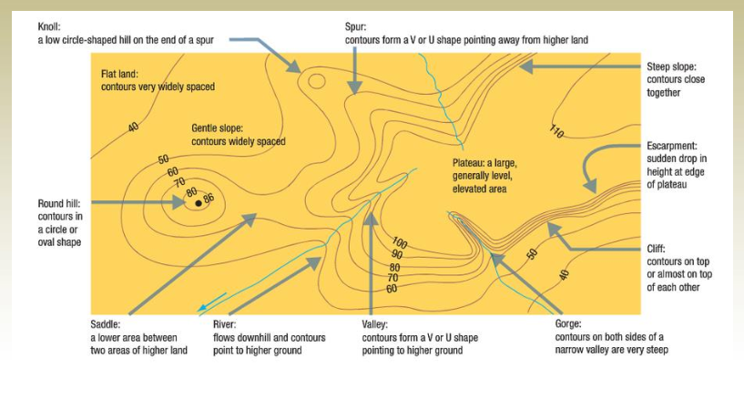
9. Contour line spacing indicates ground sloping
- Widely spaced contour indicate flat surface (a)
- Closely spaced contour indicates steep ground (b)
- Equally spaced contour indicates uniform slope(c)
10. Contour lines are not shown going through the buildings
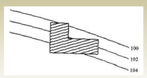
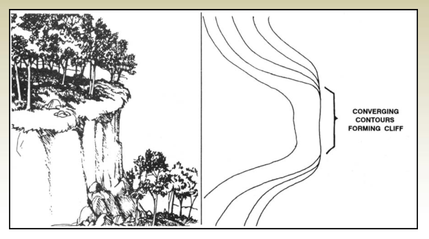
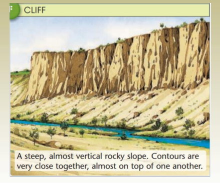
11. Contour lines cannot unite or cross each other except for two cases:
a. They will meet at a vertical cliff,
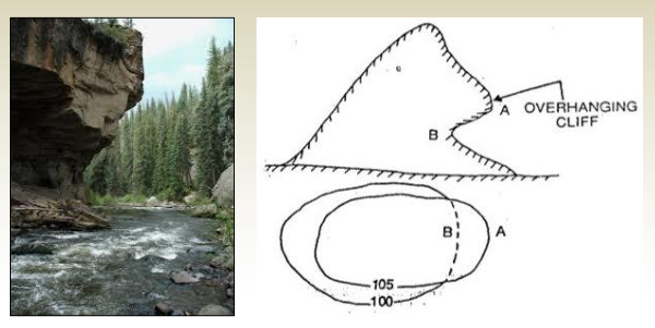
11. Contour lines cannot unite or cross each other except for two cases:
b. They will overlap at a cave or overhang. When contour lines overlap, the lower elevation contour should be dashed for the duration of the overlap
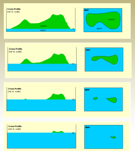
Summary
Uses of Contour Maps
- Construct longitudinal sections and cross-sections for initial investigation.
2. Intervisibility of points
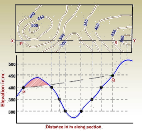
- Outline and measure of drainage areas/watershed delineation.
4. Compute volumes.
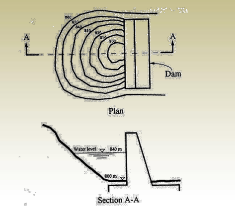
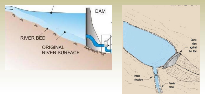
- Define the limits of constructed dams, road, railways, tunnels, etc.
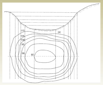
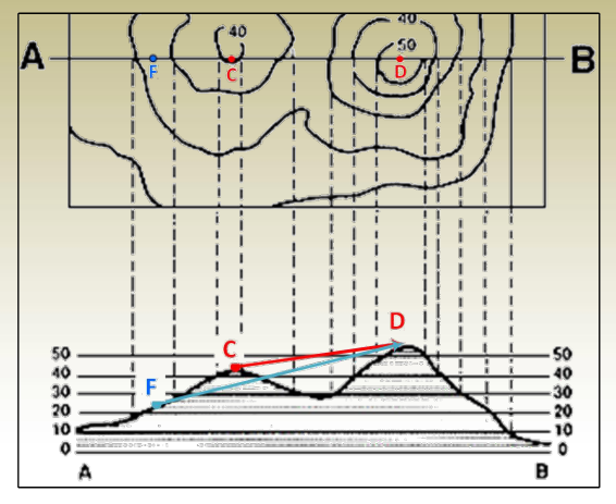
Contour Map Reading
Guidelines for Reading Contour Maps:
- Determine the highest and lowest elevations to understand the total elevation range in the area.
- Observe the slope direction — elevation increases indicate an uphill slope, while decreases show downhill movement.
- Analyze the steepness of the terrain — closely spaced contours mean steep slopes; widely spaced ones show gentle or flat areas.
- Recognize landform shapes — contour patterns reveal features like hills, valleys, ridges, or rounded and sharp-edged terrain.
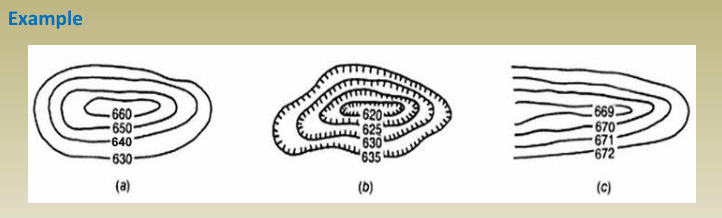
- In Figure (a), the terrain is steepest due to a 10-meter contour interval, showing rapid elevation change.
- In Figure (c), the land appears flattest, as the 1-meter contour interval reflects gradual slope changes.
- Rising contour elevations in Figure (a) suggest the presence of a hill.
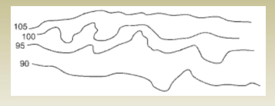
- In Figure (b), the contours show decreasing elevations toward the center, indicating a depression or sinkhole.
- In Figure (c), the elevation drops along the contour lines, which means it’s a valley. If the elevation pattern were reversed, the same shape would represent a ridge.
Construction of Contouring Maps
- Data collection
- Contour computations
- Contour map drawing
Contouring Data Collection: Grid Leveling
- The process of collecting height information to draw contour maps.
- Cover the whole area with a mesh (grid) of square cells
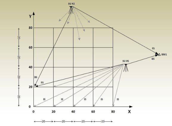
- All readings are filled in a differential leveling table where the elevations of points are computed. Computational checks must be made and misclosures adjusted
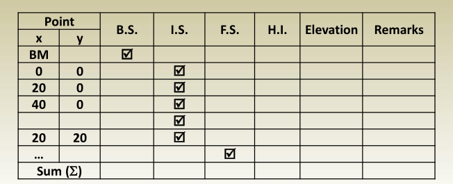
Notes:
- Points are identified according to their coordinates (x, y).
- Most points in grid leveling are I.S.
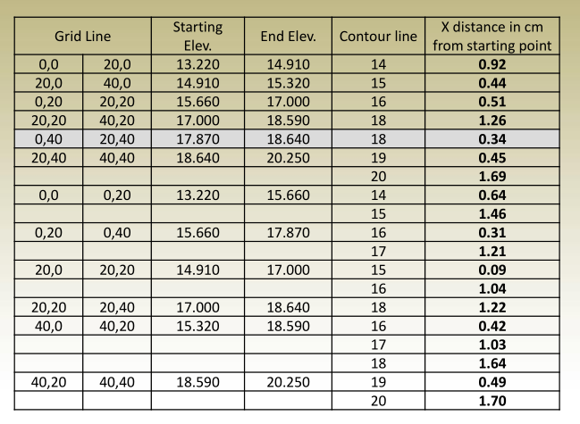
Contour Computations and Drawing
- Plot the grid to the scale of the map, and the levels of the grid corners are entered.
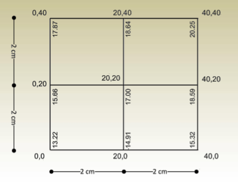
- Identify minimum elevation and maximum elevation of the grid points to determine contour lines with consideration of the contour interval.
Mini. contour > Mini. elevation & Max. contour < Max. elevation
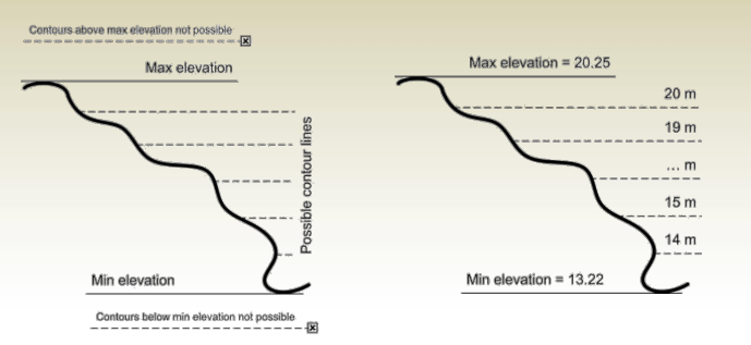
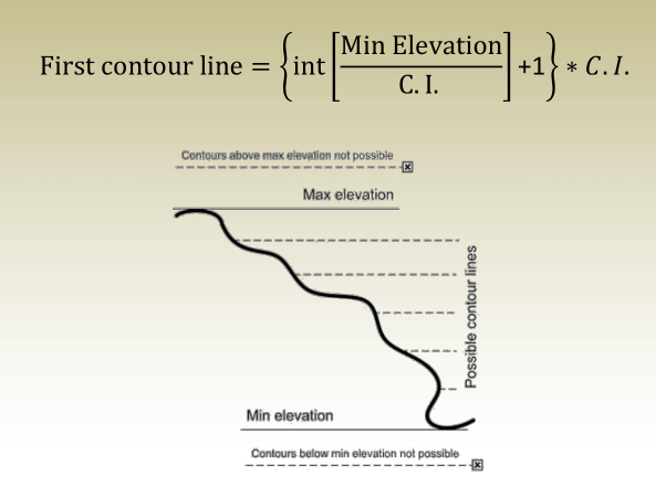
- First contour passing through an area
2. Last contour passing through an area
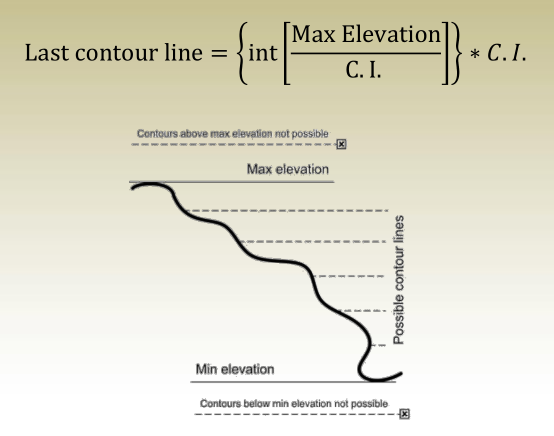
- Find the exact location of contour points on all grid lines, and then connect between points of the same elevation. e.g.: To determine the location of contour points on the first grid line:
1. possible point has an elevation 18.
2.its location can be determined from: