Connecting Objects and Styles
The word “object” is often considered generic, but in the context of Civil 3D, it has a very specific meaning. A Civil 3D object is an intelligent component of your design model. It stores information about itself and can interact with other objects within the drawing.
Another defining feature of a Civil 3D object is its connection to a Civil 3D style. A Civil 3D style is a collection of settings that determine the object’s appearance and behavior.
The relationship between objects and styles is one of the key concepts you need to understand to effectively use Civil 3D. Here are some examples of Civil 3D objects that you will encounter in both this course and real-world production environments:
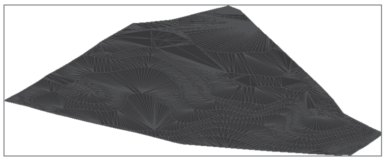
- Surface: A 3D model used to represent the ground’s shape, whether existing or proposed.
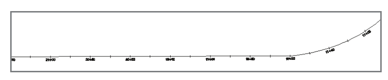
Alignment
An Alignment in Civil 3D is a series of 2D lines, arcs, and spirals that are used to represent linear features, such as the centerline of a road. Alignments form the foundation of many design workflows in Civil 3D, serving as a reference for profiles, corridors, and other design components.
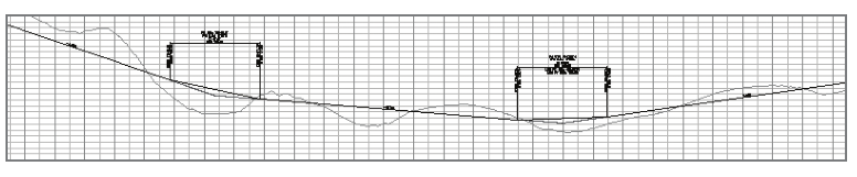
Profile
A Profile in Civil 3D is a series of lines and curves that depict elevation changes along an alignment. Profiles are essential for visualizing and designing vertical elements of linear projects, such as roadways, pipelines, or railways. They work in conjunction with alignments to provide a complete representation of the design in both horizontal and vertical dimensions.
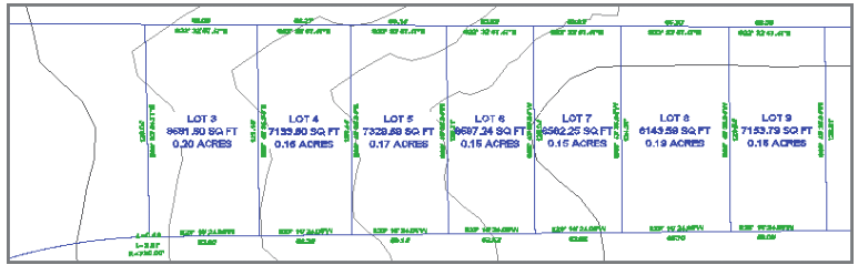
Parcel
A Parcel in Civil 3D is a closed shape that is typically used to represent a legal property boundary. Parcels are essential for land development and cadastral workflows, enabling the creation and management of property divisions, lot layouts, and ownership details within a design model.
Recap of Important Definitions
- Civil 3D Object: An intelligent component of your design model that stores information about itself and can interact with other objects in the drawing.
- Civil 3D Style: A collection of settings that determine the appearance and behavior of a Civil 3D object.
What is Elevation?
The term elevation refers to the vertical height of a point relative to a reference surface, such as sea level. If you’re new to civil engineering or surveying, an easy way to visualize elevation is by imagining a piece of grid paper spread over a piece of land.
- Horizontal Lines (X and Y): Represent directions running west to east and south to north.
- Elevation (Z): Represents height coming straight up out of the paper. For example, the top of a hill would have a higher elevation than the bottom of a ravine.
In the context of an XYZ coordinate system:
- X and Y represent horizontal positions, while Z represents elevation.
In Civil 3D, which integrates general AutoCAD® functionality with civil engineering tools, elevation corresponds to the Z-axis.
Note: Depending on your region, the term “level” might be used interchangeably with “elevation.”
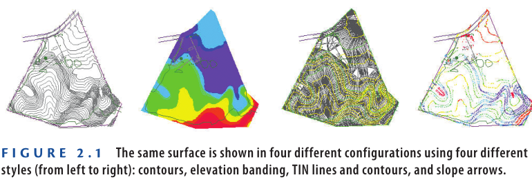
Each object in Civil 3D can be controlled and customized through styles. For instance, surface styles allow you to display a surface in various formats, such as:
- Contour lines
- A 3D grid
- Arrows indicating downhill slopes
- Shading to represent different elevation ranges, and more (see figure 2.1).
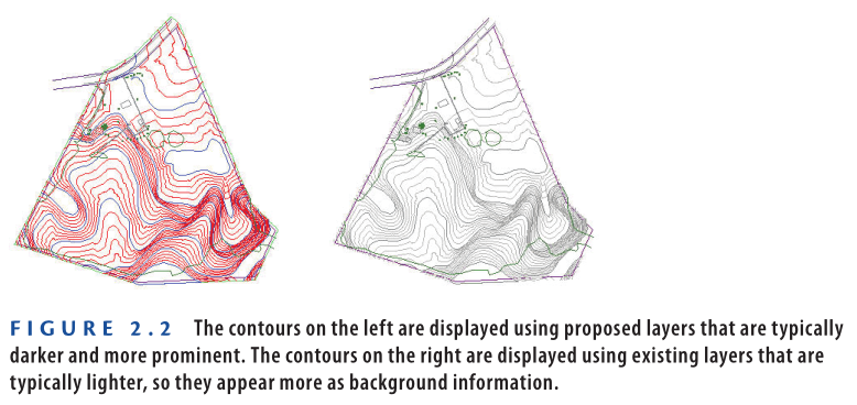
Styles not only control the overall appearance of an object but can also manage specific details that differ slightly between similar configurations. For example:
- One case may display surface contours on an existing layer.
- Another case might display the same contours on a proposed layer (see figure 2.2).
While the configuration (contours) remains the same, the way it is displayed—such as which layer it is assigned to—can differ based on the style.
Exercise 2.1: Apply Styles to Objects
In this exercise, you will use styles to modify the appearance and behavior of Civil 3D objects. Follow these steps to apply different surface styles:
- Open the Drawing:
- Open the drawing named Objects and Styles.dwg which you can download from the Youtube video description below.
- The plan view of the surface in the left viewport should resemble the first image in Figure 2.1.
- Select the Surface Object:
- Click on one of the contour lines in the drawing to select the surface object.
- Display the Properties Palette:
- If the Properties palette is not visible, click Properties on the Home tab of the ribbon.
- Change the Style to Elevation Banding (2D):
- In the Properties window, change the Style property to Elevation Banding (2D).
- The surface will now display as colored bands, representing different ranges of elevations, similar to the second image in Figure 2.1.
- Change the Style to Contours & Triangles:
- Change the Style property to Contours & Triangles.
- The surface should now appear as shown in the third image in Figure 2.1, with triangles forming the basic framework of the surface.
- Change the Style to Contours 1′ and 5′ (Design):
- Change the Style property to Contours 1′ and 5′ (Design) (0.5 m and 2.5 m (Design)).
- The surface should now resemble the left image in Figure 2.2.
- Change the Style to Contours 1′ and 5′ (Background):
- Change the Style property to Contours 1′ and 5′ (Background) (0.5 m and 2.5 m (Background)).
By following these steps, you can see how different styles affect the appearance and display of surface objects in Civil 3D.
What Are Contours?
Contours are lines used to represent changes in elevation or topography across the ground. You may have seen contour lines on trail maps, which cover a large area (such as square miles or square kilometers). In Civil 3D, these lines help visualize changes in elevation in a more detailed, localized context.
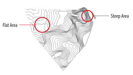
By definition, contours are lines that connect points of equal elevation. Imagine passing a giant horizontal blade through the ground at equal elevation intervals—you would end up with contour lines.
- In flat areas, the contour lines would be spaced far apart.
- In steep areas, the contour lines would be closer together.
With practice, you can look at a contour map and visualize the 3D shape of the land it represents.
Note: Whenever referring to figures, remember to include their number and description as indicated.
- Edit Surface Style:
- With the surface still selected, click the Tin Surface: Existing Ground ribbon tab.
- Then click Surface Properties ➢ Edit Surface Style.
- Modify Major Contour Color:
- In the Surface Style dialog box, click the Display tab.
- Click the color column next to Major Contour.
- Choose a Color:
- Select a noticeable color for the major contour lines and click OK.
- Return to the Drawing:
- Click OK again to return to the drawing.
- Save and Close the Drawing:
- Save and close the drawing once you’ve completed the exercise.
Note: You can view the results by opening the Objects and Styles – Complete.dwg drawing file.
https://www.mediafire.com/file/v9lkn7ushhv7c5m/Objects+and+Styles+-+Complete.dwg/file
Watch Complete Video for this Exercise here
Reflection:
As you completed the exercise, you may have noticed that no extra steps were required to update or redraw the surface after assigning a new style or editing the style. The change was immediate. This happens because of the dynamic relationship between the object (surface) and its style. When the style is modified, the software automatically updates the appearance of the object without requiring additional steps.
Editing a Style vs. Assigning a Different Style
In the previous exercise, steps 4 through 7 demonstrated how to change the appearance of the surface by assigning a different style. This is the most common way to modify an object’s appearance in Civil 3D, and it will likely be your approach 99% of the time.
In steps 8 through 10, you edited the style that was already assigned to the surface. Editing styles is typically the responsibility of a CAD manager or someone in charge of maintaining consistent standards across a project. In many companies, end users are not permitted to create or modify styles directly.
However, it is important to understand that when a style is modified, any object that is using that style will automatically update to reflect the changes. This dynamic behavior ensures that the style is consistently applied across all objects in your drawing, and the object will change its appearance or behavior based on the new version of the style.
Connecting Labels and Label Styles
Labels are crucial in design as they provide specific information necessary for construction. Civil 3D allows you to create various types of labels associated with different Civil 3D objects. Labels are also Civil 3D objects, and just like other objects, their appearance and behavior are controlled by styles. When you modify or assign a new style to a label, it reacts in the same way as other objects in the design.
Here’s an example of a label type:
- Surface Spot Elevation label: Used to display the elevation of a key point in the design, such as a low point where water will drain toward or a high point where water will drain away from.
Alignment Station Offset label: This label type is used to indicate the location of a feature in relation to a linear object. For example, it can be used to express the location of a manhole by specifying its distance along the road’s length (station) and its offset to the left or right of the road.
Profile Grade Break label: This label type is used to show the location and elevation of a slope change along a profile. For example, if the profile slopes upward and then changes to a downward direction, the highest point of the change is considered a grade break, which is a common location for placing a label.
Station and Offset
In long linear designs like roads and pipelines, station and offset notation is used to express locations. Stations are typically represented in a special format with a plus sign.
- Imperial units: A station of 2+00 refers to a location that is 200 feet down the road (starting at station 0+00). To reach station 2+00, offset 12′, you would travel 200 feet down the road, then turn right 90 degrees and travel 12 feet.
- Metric units: In this case, a station of 0+200 refers to a location 200 meters down the road. To reach station 0+200, offset 4 m, you would travel 200 meters down the road, turn right 90 degrees, and travel 4 meters.
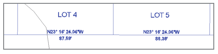
Parcel Segment label: This label type is used to express geometric information about a line or curve that forms part of a legal boundary. For example, it is common to label the bearing and distance of a straight line segment along a property boundary.
Exercise 2.2: Apply Label Styles to Labels
- Open the drawing named Labels and Styles.dwg which you can download from Youtube video description below.
- In the top-right viewport, click the label. If the Properties palette is not visible, click Properties on the Home tab of the ribbon.
- Change the value for Station Offset Label Style to Station and Offset, as shown in Figure 2.3. You will notice that the content of the label changes accordingly.
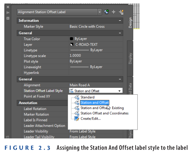
4: Change the value for Station Offset Label Style to Station and Offset – Existing. This time, while the content remains the same, the style of the text changes.
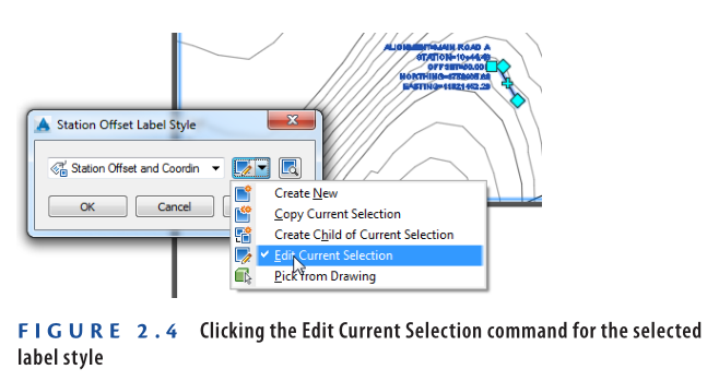
5: With the label still selected, click Label Properties ➢ Edit Label Style on the Labels – Alignment Station Offset Label contextual ribbon tab.
6: In the Station Offset Label Style dialog box, click Edit Current Selection, as shown in Figure 2.4.
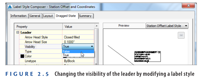
7: In the Label Style Composer dialog box, click the Dragged State tab. Change the Visibility value for the leader to False, as shown in Figure 2.5.
- Click OK twice to dismiss all dialog boxes and return to the drawing.
- Save and close the drawing.
You can view the results of successfully completing this exercise by opening Labels and Styles – Complete.dwg.
https://www.mediafire.com/file/thaul2xgupepy62/Labels+and+Styles+-+Complete.dwg/file
Watch Complete Video here for this Exercise:
Styles and Company Standards
Civil 3D styles can help end users meet company standards and ensure more consistent graphical output. With a well-defined set of styles that integrate company standards, users only need to choose the appropriate style from a manageable list. On the other hand, if end users are required to create their own styles, labels, or other graphical components, the resulting drawings may vary and might not comply with company standards.
Connecting objects to objects in Civil 3D is crucial for managing relationships in a design. As projects often involve interconnected mini-designs, such as roads, drainage systems, and utilities, Civil 3D allows these objects to be related. For instance, if a road’s centerline needs modification, the related changes in elevation, lanes, curbs, sidewalks, and drainage ditches are automatically adjusted.
Before Civil 3D, any change had to be manually traced and adjusted in various elements, risking time, money, and errors. With Civil 3D, these relationships are dynamic, enabling automatic updates across all connected elements, thus improving efficiency and reducing human error.
Exercise 2.3: Explore Object Relationships
- Open Object Relationships.dwg which you can download from the Youtube video description below.
2: Press the F3 key, and observe the command line. If it reports <Osnap On>, press F3 again. If it reports <Osnap Off>, this is the correct condition for this exercise, and you can move on to the next step.
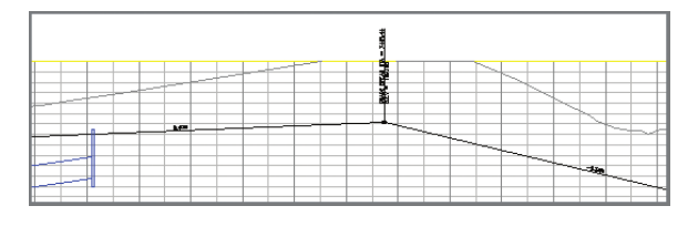
3: Click the top-right viewport, which shows a profile of the road design. The black lines represent the elevations along the centerline of the new road, and the blue lines represent storm drains and pipes connecting them.
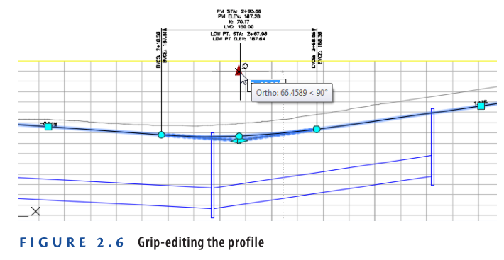
4: Click the black line representing the road profile. Zoom in until you can clearly see the triangular grip located at the intersection of two lines.
5: Click the triangular grip, and drag it upward to a location just below the top edge of the profile view grid, as shown in Figure 2.6. Notice that the 3-D view (bottom-right) of the road automatically updates, including the height of the Inlet 2 drain. In the profile view (top-right), the top of the drain is elevated to match the road.
Save and Close the Drawing:
6: Save the drawing and close it.
You can view the results by opening Object Relationships – Complete.dwg.
https://www.mediafire.com/file/2px1bh1if0bbjjd/Object+Relationships+-+Complete.dwg/file
Watch Complete video here for this Exercise:
Understanding Object Relationships in Civil 3D
This exercise illustrates the power of object relationships in Civil 3D. When the triangular grip location was changed, several automatic updates occurred:
- The slopes of the lines leading to the grip were adjusted.
- Parabolic curve geometry at the grip location was updated.
- The road corridor object was rebuilt and updated to match the new profile.
- The surface representing the road’s pavement and embankment was automatically rebuilt.
- The storm drain’s top elevation updated to match the new surface.
- The 3D representation of the storm drain and profile view automatically updated.
This demonstrates the efficiency of the Civil 3D dynamic environment. A simple edit triggered multiple changes that would have taken much longer manually. However, such relationships must be consciously established during the design process.
Connecting Objects to Labels
Labels in Civil 3D are essential for construction documentation but are not directly tied to the design. With dynamic object-label relationships, labels automatically update as the design changes, ensuring they always reflect the latest information without needing manual updates.
Exercise 2.4: Explore the Relationship Between Objects and Labels
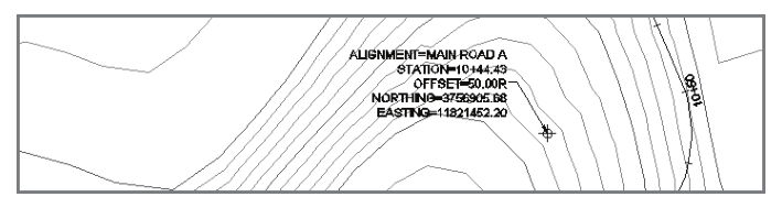
- Open Objects and Labels.dwg from Youtube video description below. Notice the elevation label displaying 190.02 (57.92).
- Select one of the dark gray contour lines. On the ribbon, click Edit Surface ➢ Paste Surface.
- Choose Main Road A FG, and click OK. Press Esc to clear the selection. The label in the top-right viewport should update to 187.33 (57.07).
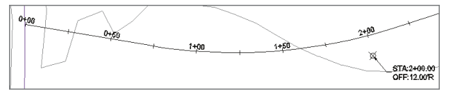
- In the top-right viewport, pan south and observe the station value 10+95.68 (0+333.96) and the offset value 68.49L (20.88m L) in the label.
- Select the road centerline and drag the triangular grip to the west near the west edge of the road, as shown in Figure 2.7.
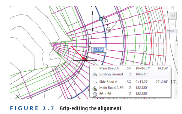
6: After a brief pause while Civil 3D rebuilds several aspects of the design, the label updates again. Since the road no longer influences the elevation of this spot, the label reverts to its original value of 190.02 (57.92). The station offset label now reflects updated values for station and offset.
7: Save and close the drawing.
You can view the results of successfully completing this exercise by opening Objects and Labels – Complete.dwg.
https://www.mediafire.com/file/7tpgw9qxgt9n8d6/Objects+and+Labels+-+Complete.dwg/file
Watch Complete video here for this Exercise:
The evolution of land development design from simple 2D drawings to dynamic 3D models represents a significant advancement in the field. Civil 3D enables designers to create intelligent, 3D models of the components that make up a land development project. Unlike traditional 2D drawings, these models store not only spatial information but also additional data such as material properties and flow characteristics, offering a much more comprehensive and versatile representation of the design.
With tools like Civil 3D, the 3D models allow for real-time updates and changes. For example, a stormwater pipe in a design can be modeled as a 3D object with specific characteristics, allowing hydraulic analysis to ensure that it meets design criteria. This makes the process more accurate and efficient than traditional methods.
Despite the advanced capabilities of 3D design tools, many users still focus on creating basic 2D drawings. However, leveraging the full potential of Civil 3D’s dynamic relationships can lead to more efficient workflows, fewer errors, and better project outcomes. The investment in 3D dynamic models will pay off in every project by automating updates and maintaining consistency across the entire design.
Building Information Modeling (BIM)
It has transformed the design, construction, and facilities management industries, and while Civil 3D might not directly handle the “building” aspect, it plays a significant role in the “information” and “modeling” parts. Many civil engineering projects, like roads, drainage systems, and utilities, are integral to building construction and can be seamlessly integrated into BIM workflows. Without accurate models, BIM would not be possible.
GPS-Guided Machine Control
is a great example of how Civil 3D models can be used in construction. By uploading Civil 3D models to GPS-guided earthmoving machinery, these machines use real-time GPS data to match the dimensions of the terrain with the model, ensuring precision in excavation and other tasks. This eliminates the guesswork and allows construction to proceed with accuracy and speed.
Construction Simulation
offers the ability to plan a project before it begins, allowing contractors to test and simulate construction sequences and staging. This can prevent costly errors by highlighting issues before they happen in the real world. This “4-D” (3-D + time) or “5-D” (3-D + time + cost) simulation helps predict the project’s execution, including material handling, equipment placement, and even cost tracking.
Visualization is another key benefit of working with dynamic 3D models. Clients and stakeholders now expect to see 3D renderings or animations to better understand the design. Having these models ready for visualization can make presentations more impactful and engaging, helping to get approvals or raise awareness for the project.
Building designs as dynamic models might take extra time initially, but the benefits in terms of accuracy, data richness, and client satisfaction are immense. Dynamic models improve design quality and efficiency, offering faster responses to changes and reducing overall costs. Designers who fully leverage these tools create better designs and have more flexibility, leading to improved business outcomes.
Sharing Data in a Dynamic Environment is another crucial aspect of Civil 3D. When multiple team members work on different parts of a project, Data Shortcuts allow those designs to interact with each other. For instance, a profile created by one person in one drawing can be used by another person working on the road model or drainage system. This enables teams to collaborate efficiently, ensuring that all parts of the design stay connected and updated in real-time.
Data shortcuts simplify managing and sharing project data between multiple drawings, making collaboration smoother and reducing the risk of errors. This functionality, along with dynamic models, represents the future of efficient and accurate design in land development projects.
Data Shortcuts and Data References
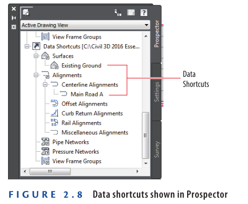
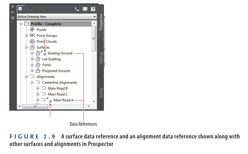
Once a data shortcut is made available, you can use it to create a data reference in another drawing. Objects that are data referenced, such as surfaces, alignments, and profiles, appear in Prospector along with other “native” objects. An icon next to them indicates that they are data references. In the example, (figure 2.9) the Existing Ground surface and the Main Road A alignment have an icon next to them indicating that they are data references.
Exercise 2.5: Share Data using Data Shortcuts
In this exercise, you will use data shortcuts to share data between drawings by publishing a surface and an alignment as data shortcuts from two separate drawings, and then referencing them into a third drawing to create a profile.
- Open the file named
Surface.dwgwhich you can download from Youtube video description below. - If the Toolspace is not visible, click Toolspace on the Home tab of the ribbon.
- On the Prospector tab of the Toolspace, right-click Data Shortcuts and select Set Working Folder. The Browse For Folder dialog box opens.
- Browse to the Chapter 02 class data folder, and select Sample Working Folder. Click OK.
- Right-click Data Shortcuts, and select New Data Shortcuts Project Folder. The New Data Shortcut Folder dialog box opens.
- Type Sample Project in the Name field, and click OK.
- Save the drawing. Click the Manage tab of the ribbon, and then click Create Data Shortcuts. The Create Data Shortcuts dialog box opens.
- Check the box next to Existing Ground, and click OK.
- Open the file named
Alignment.dwglocated in the Chapter 02 class data folder. - Repeat steps 7 and 8 for the alignment named Main Road A.
- Open the file named
Profile.dwglocated in the Chapter 02 class data folder. - In Prospector, expand Data Shortcuts → Surfaces. Right-click Existing Ground, and select Create Reference.
- Click OK to accept the default settings in the Create Surface Reference dialog box. Contours in the left viewport and a 3-D model in the lower-right viewport indicate a newly added surface.
- Repeat steps 12 and 13 for the alignment data shortcut named Main Road A. A new alignment is created in the drawing.
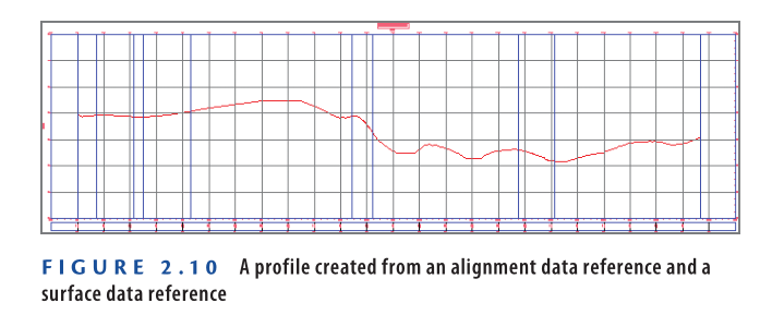
15. On the Home tab of the ribbon, click Profile → Create Surface Profile. The Create Profile From Surface dialog box opens.
16. Click Add, and then click Draw In Profile View. The Create Profile View – General dialog box opens.
17. Click Create Profile View. Pick a point in the top-right viewport. A new profile is created that results from relating an alignment to a surface. This profile represents the interaction among three different drawings.
18. Save and close all drawings.
You can view the results of successfully completing this exercise by opening Profile – Complete.dwg.
https://www.mediafire.com/file/zn7uhgvb93lyu0m/Profile+-+Complete.dwg/file
Watch complete video here for this Exercise:
Now You Know
Now that you have completed this chapter, you understand the dynamic environment of Civil 3D. You comprehend how styles are applied to objects to change their appearance and behavior. This includes objects such as alignments, surfaces, and labels. You understand how objects are connected to one another and interact automatically so that you don’t have to spend extra time “fixing” your design when something changes. You appreciate the richness of a 3-D model and understand how powerful it is for performing design in today’s fast-paced and demanding world. Finally, you can share data within a team by using data shortcuts to share design data between drawings.
Now that you understand and appreciate the dynamic Civil 3D environment, you will move forward into the next chapters with greater insight. As you progress through this book, be on the lookout for instances where this dynamic environment offers power and efficiency. Remember these examples and take them with you when you begin designing your own projects using Civil 3D.
All Exercises of Chapter-2: